DEEPWATER OPERATIONS: Deepwater UBD 10,000 psi choke regulates casing pressure automatically

If well control operations could be performed flawlessly, conventional chokes would control the bottomhole pressure within acceptable limits. However, significant variations in the bottomhole pressure occur, primarily the result of the operating charac-teristics of conventional chokes. In the past, choke manufacturers have recognized this problem and tried to overcome these drawbacks inherent with the conventional choke control systems by developing "auto" choke controllers - with some success.
A conventional well control choke is a remotely controlled valve with some type of adjustable orifice arrangement. The orifice size can be changed from full close to full open by manipulating a control device located in a remote console. In most cases, this control device has a lever or handle. Therefore, the conventional choke will be referred to as a joystick choke.
A pressure drop is created across the adjustable orifice when fluid flows through the choke. The fluid is throttled to establish an annulus pressure on the wellbore and controlled to any desired value by manipulation of the choke orifice. However, the annulus or casing pressure is subject to change without adjusting the orifice size, because of fluid property changes such as density, viscosity, and change of state from liquid to gas. These pressure fluctuations require precise manipulation of the orifice to maintain the desired casing pressure.
Breaking circulation
When breaking circulation, the first objective during a well control operation is to hold the casing pressure constant while bringing the mud pump up to the selected rate. This is a trial-and-error procedure, so it must be done relatively slowly, requiring skill by the choke operator to achieve good pressure regulation.
When the desired pumping rate is reached, the focus is switched to drillpipe pressure control. The best way to hold bottomhole pressure constant is to circulate the well using the drillpipe pressure as a control. However, there are cases when variations from constant drillpipe pressure are required, such as in the transition during a wait-and-weight procedure, when kill mud is pumped down the drillstring.
During the remainder of the well control operation, the observed drillpipe pressure may not remain at the desired value. The best remedy for drillpipe deviation is to change the casing pressure with the choke. However, if the choke orifice is manipulated while watching the drillpipe gauge for response and correction, over-control will result due to the well lag time. In other words, by the time the change made to the casing pressure reaches the drillpipe gauge, the casing pressure will be over-corrected.
Too much, too little
This leads to over-control and under-control of the casing, drillpipe, and bottom hole pressures. The proper technique is to observe the deviation of the drillpipe pressure, and manipulate the joystick by trial and error, such that a correction is made to the casing pressure equal to the drillpipe deviation. Joystick manipulation should stop while the casing pressure correction is transmitted down the annulus and up the drillstring. If the correct pressure deviation is made to the casing pressure, the drillpipe pressure should return to its correct value.
Even if the pumping rate is held constant during a well control operation, a gas kick will cause the fluid flow rate through the choke to vary greatly due to gas expansion. This large change in fluid flow rate will require continuous changes to the choke orifice size (and the casing pressure) to maintain the drill pipe pressure.
When a gas kick reaches the surface, dramatic changes in orifice size are required as slugs of mud and gas pass through the choke. These slugs occur abruptly and tax the skill of the choke operator to adjust the casing pressure to stabilize the drillpipe pressure. Assuming the casing pressure is instantaneously correct while mud is in the choke, a slug of gas entering the choke will cause the casing pressure to drop quickly, the observed drillpipe pressure still looks normal due to the well lag time. If the choke operator focuses his attention only on the drillpipe gauge, he may fail to notice the change in casing pressure until a belated drop in drillpipe pressure occurs.
When the casing pressure decreases, correcting for a deviation in drillpipe pressure is difficult to achieve since the casing pressure is currently incorrect. Making a correction based on the improper casing pressure is not likely to result in proper drillpipe pressure correction.
What's normal?
Assuming the casing pressure is instantaneously correct while gas is in the choke, a slug of mud entering the choke will cause the casing pressure to rise quickly, the observed drillpipe pressure still looks normal due to the well lag time. The choke operator must respond quickly to each change from mud slug to gas slug by joystick manipulation to adjust the casing pressure.
In most cases, the choke operator does not have time to stabilize the casing pressure between alternate mud and gas slugs. It is extremely difficult to correct for deviations in drillpipe pressure during these times of undulating pressures. Therefore, the bottomhole and drillpipe pressures suffer these same undulations. This process is further compounded by the fact that well lag time has now increased, exaggerating the out-of-phase relationship between pressure deviation, correcting action and response in drillpipe pressure. During these periods, the hole is highly vulnerable to breakdown or secondary bubble influx.
Debris entering the choke will reduce the fluid flow rate and increase the casing pressure. The debris may partially or completely plug the choke. The operator must respond quickly to open the choke to clear the debris and then quickly close the choke to maintain the proper casing pressure. The hole is again highly vulnerable to breakdown or secondary bubble influx, due to rapid over-pressure or under-pressure usually experienced in clearing the choke of foreign material.
Design objectives
To overcome these unfavorable operating characteristics and to provide more stable, accurate and predictable pressure control, the following design objectives for a new type of choke were formulated:
(1) Should eliminate manual orifice manipulation by choke operator
(2) Provide automatic pressure regulation at selected casing pressure, when breaking circulation for mud pump starting/stopping
(3) Make accurate and predictable casing pressure changes to provide precise drillpipe pressure control
(4) Provide automatic pressure regulation during periods of mud and gas slugging
(5) Maintain casing pressure regulation when debris enters the choke
(6) Provide positive shut-off when either mud, gas, or water passes through the choke, even after the trim components experience erosive wear
(7) Designed to minimize wear on internal trim components
(8) Provide easy access to internal parts of choke for fast inspection/servicing
(9) Provide automatic pressure control and fluid displacement during pipe stripping and snubbing operations
(10) Permit good back-pressure control for under-balanced drilling while maintaining casing pressure, yet passes cuttings through the choke
(11) Provide easy interface for computer control
(12) Provide the possibility of operating with the choke mounted SubSea on the BOP stack.
A choke that provides automatic pressure regulation will satisfy each of the above listed design objectives.
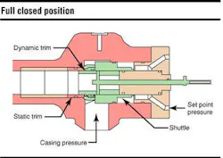
UBD-10 choke
The final design of the under-balanced drilling (UBD)-10 choke incorporates a sliding shuttle within the choke body that is connected to a dynamic trim sleeve. This shuttle assembly slides back and forth into a matching static trim sleeve to form a circular orifice that controls the flow of fluid or gas from the well. The hydraulic set-point pressure applied to the backside of the shuttle assembly is adjusted by a pressure regulator and measured by the hydraulic set point gauge located on the choke control panel. Casing pressure is applied to the front side of the shuttle assembly.
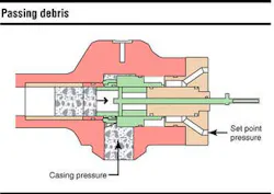
The shuttle choke maintains good pressure control when cuttings or debris are present in the circulating fluid. Debris that plugs the orifice will increase the casing pressure. This will cause the shuttle assembly to move, increasing the orifice size, to maintain the casing pressure at the hydraulic set-point pressure. In so doing, some or all of the debris will be discharged through the choke orifice.
If the trash cannot pass through the orifice, the choke is designed to accommodate considerable buildup in the housing before a manual clean-out operation is required. These two features are ideal for maintaining desired casing pressures for under-balanced drilling operations. This choke operates differently from other chokes. The amount the choke is open or closed is not important during normal operations. The choke automatically adjusts the size of the orifice to compensate for any changes in the casing pressure.
The standard practice for stripping drillpipe out of the hole is to calculate the displacement for each stand of drillpipe and convert this value to an equivalent number of pump strokes. As the pipe is pulled from the well, the mud pump is operated for the required number of strokes.
There is another method available to the operator using the shuttle choke: Adjust the set-point pressure equal to the shut-in casing pressure and start the mud pump at a slow pumping rate. The choke will automatically open and allow the excess fluid to flow from the well. As the drillpipe is pulled from the hole, the choke will partially close, allowing the mud to replace the volume of the pulled stand of drillpipe.
Conclusion
Design objectives for this type of choke have been realized:
- Better bottomhole pressure control is provided by the automatic pressure regulation.
- Circulation startup and stopping does not require operator manipulation of the choke.
- Mud-gas slugging does not require operator manipulation of the choke and casing pressure remains stable during this time. This provides a stable casing pressure from which precise, quick correction of drillpipe pressure deviations can be made.
- Positive shut-in of the well is reliable with mud, gas, or water.
- The choke can clear or tolerate large quantities of debris or cuttings and still provide good pressure regulation during well control or underbalanced drilling operation.
- Trim wear is negligible in the vital control areas, yet good pressure control can still be provided in case of trim wear or dramatic trim breakage.
- Automatic pressure control and fluid displacement during stripping and snubbing operations has been effective.
- Reduction in operator control manipulation has been reduced to startup pressure selection and simple, precise incremental correction of drillpipe pressure deviations.
- Quick and easy access to the internal components of the choke body has been provided.
- Closed loop computer control has yet to be executed with this choke.
- Preliminary efforts have been expended toward subsea blowout preventer stack installation and control, and the fact that total control of the choke requires only one small pressure conduit, makes this application possible.
Acknowledgement
Many of the issues introduced in the technical paper entitled "Unique Well Control Choke: Design Objectives vs. Commercial Field Performance," written by L. L. Cain were incorporated in this paper. Cain was instrumental in the design of the UBD-10 choke. He is now deceased, and this paper is dedicated to him.