Seng Hock Teo
Jim Adams
Geoff Ashcombe
BP Exploration Operating Co.
In the drive to improve the economics of deepwater tieback projects, direct electrical heating (DEH) of pipe-in-pipe (PIP) production flowlines has been identified as a potential technology to improve commerciality though lower capex and improved operational efficiencies.
The strategic value of DEH is considered to be high, since it can potentially enhance the economic value of deepwater developments. Key value enablers have been categorized as follows:
- Single flowline tieback – no requirement for service flowline/riser for displacement
- Operating efficiency improvement from:
- –Simplicity of operation
- –Reduction of hydrate formation risk during shutdown
- –Faster re-starts
- –No requirement for displacement fluid and its associated storage
- –Maintenance of crude value compared to potential reduction that could arise from displacement fluid "contamination"
- Possible hydrate remediation.
The goal here is to describe a recent calibration trial undertaken to qualify the concept of DEH PIP and its key components for deepwater applications. The objectives of the trial were to:
- Calibrate computer analytical models against measured field data
- Demonstrate and verify the concept for uniform heating – avoidance of "hot spots"
- Measure and confirm thermal performance of the DEH system in a submerged environment
- Examine heating performance with varied electrical supply frequencies (60, 120 and 200 Hz) and voltage settings
- Determine heating limits – heat rates and feasible tieback distances
- Assess inherent safety.
Additional DEH PIP features include the potential for:
- Use of surplus or emergency power from host facilities
- Wax and/or hydrate management of low temperature fluids during normal operations.
The work scope undertaken was comprised of all engineering, fabrication, installation, commissioning, and operations necessary for the field trials.
Demonstrating the concept
While already used successfully primarily in shallower water, several factors led BP to conduct physical trials to demonstrate the concept, its viability and calibration of design tools. These factors included a lack of publically available technology development and performance data – such as DEH calibration with theoretical understanding, and its science; the impacts on operational safety and environment; and electrical leakage/corrosion.
The electrical flowline heating technology selected for the calibration trial was DEH PIP center-fed. The drivers leading this selection for deepwater developments are related to:
- Long cooldown time requires insulation of U-value ≤ 1 W/m2·K
- Hydrate prevention and mitigation
- Better availability than fluid displacement
- Potential for continuous heating service
- No additional anode consumables
- Compatible with hybrid risers, turret moored hosts and SCRs
- Multiple heated segments between drill centers and manifolds
- Future expandability.
Examining the technology
The technology chosen to fulfil the above drivers was DEH PIP center-fed, where the electrical current flow splits two ways at the power input connection (PIC) and travels along two parallel flowline circuits from either side of the PIC defined by outer pipe, end shorting bulkheads and inner pipe.
The majority of the flowing current and therefore heat produced is confined to the annulus surfaces. Due to the "proximity" and "skin effects," the current in the inner pipe flows in a thin layer close to its outer surface. This results in useful heat dissipation which is transferred into flowline fluid. The current in the outer pipe tends to flow close to its inner surface, thus this effect results in a small potential difference at the outer pipe/outer surface in contact with the seawater, and hence low electric field strength and negligible seawater leakage currents.
The largest potential difference seen at the exposed surfaces is at the outer pipe PIC electrical connections where the proximity and skin effects are not yet fully established. As a result, there is potential for greater electric surface field strengths and the current flows through a greater proportion of the pipe wall thickness.
Process and properties
Two line pipe material properties governing heating performance were observed in the full-scale tests and then confirmed analytically:
- Magnetic permeability determines skin depth of current flow and equivalent AC resistance
- Resistivity influences skin depth and resistance directly.
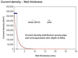
For metal, the skin depth at which the current density is 1/e (37%) times that at the surface is given by:
where:
μr = relative magnetic permeability of the material
μ0 = permeability of vacuum free space
ρ = resistivity (Ω)
f = frequency (Hz).
From this equation, it can be seen that the skin depth decreases as the frequency, while conductivity (inverse of resistivity) and permeability increase.
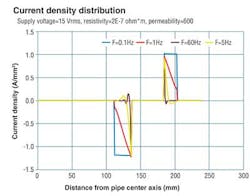
Experience indicates that current density decays exponentially across a pipe wall. This effect is seen in both the inner and outer pipes and results in a low electric field strength at the pipe wall surface in contact with the sea (on the outer pipe) and the process fluid (for the inner pipe). The exponentially decaying current density profile can be represented by a constant current density flowing through the skin depth thickness for system modeling purposes.
For this trial, research was focused on the decaying current density for a 10.75 × 16-in. PIP assembly for different applied frequencies. It was evident that the skin effect is very quickly established at frequencies greater than 1Hz. The current density is greatest at the outer surface of the inner pipe i.e. at a radius of 136 mm (5.5 in).
Current density measurements on the test models have shown that skin and proximity effects are established within a short distance of the PIC; established within 0.5 m (.019 in.) of the power connections. It should be noted that references to "losses" relate to electrical losses which, in a heater are thermal "gains." System efficiency is measured by the ratio of thermal gains divided by total power in.
DEH system power delivery is a compromise between minimizing power losses in transmission between the host source and the pipe and maximising available power at the flowline.
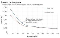
The analysis showed that the losses for a given applied voltage are approximately in proportion to the pipe diameters at higher frequencies above 60Hz. While higher frequencies benefit the heating effect by reducing the applied current (at the expense of higher voltage) required for a given heating power, the associated transmission losses and need for a higher rated power supply make this solution impractical for all but short step out distances.
The measured value of heating losses on the inner pipe at 60Hz also showed an increased loss over the losses projected from the dynamic Eddy current heating.
At reduced frequencies there is a slight increase in the ratio of inner pipe losses to total losses, which is beneficial to improving heating efficiency. DEH system power delivery is a compromise between minimizing power losses in transmission between the host source and flowline, and maximizing available power at the flowline. Use of lower frequencies could be desirable to reduce transmission losses where longer step out distances are required. However, the increased system efficiency would need to be evaluated against additional cost of using an active power supply and need for a higher subsea transformer secondary current (but lower secondary voltage) for a given heating effect. It should also be noted that there will be a practical limit on the voltage that can be applied at the pipe at the PIC or pipe-in pipe annulus.
Calibration tests
DEH PIP calibration closed loop trials have provided a number of valuable learnings about the performance of the flowline heating process, and how it compares to DEH open loop systems. The findings are briefly described below.
Heating uniformity. DEH PIP calibration tests have revealed that the current density measured on the inner pipe surface is circumferentially uniform. It is also uniform along the pipe length, where skin and proximity effects were observed to be established within a few centimeters of the electrical connections. This uniform current density will result in uniform heating to the process fluid.
Pipe electrical losses. Previous studies based the estimation of electrical heating performance primarily on dynamic electrical losses caused by conducting electrical current through a relatively thin "skin depth" in the pipe walls. Adopting this approach resulted in predicted heating efficiencies (to the pipe fluid) roughly in proportion to the inner diameter of the outer pipe and the outer diameter of the inner pipe. This could be seen, for example, with a 14.5-in. outer pipe inner diameter and 10.75-in. inner pipe outer diameter where the efficiency was expected to be approximately 57%. The theoretical power factor has been typically 0.71 and below.
Based on land impedance tests and submerged heating trials, it has been observed that the actual heating efficiency and power factors are greater than predicted. The efficiencies were typically in the region of 74% at 60Hz and power factor varied from 0.65 at lower currents and 0.75 at higher currents.
The additional losses on the inner pipe and higher power factor are believed to result from the additional heating effect from hysteresis. This results from significantly higher current density, which makes transmitting power over distance easier. When compared to DEH open loop systems, DEH PIP provides a higher efficiency and power factor system which will results in a significantly smaller topsides installation.
Frequency effects. Increasing the frequency at which power is applied results in thinner skin depth and hence a higher resistance. For a given power, the current will be lower and applied voltage higher with a higher frequency.
The major gain is that if the current is reduced to below 550A, a single pair of subsea connectors would be required at the PIC with a significant reduction in cost. The corresponding maximum heating powers at 550A are approximately 60W/m at 60Hz, 70W/m at 120Hz, and 75W/m at 200Hz.
The downside for higher frequencies is that the topsides equipment will require a variable frequency supply for frequencies other than the power generation frequency. In addition, the ability to transmit power over significant distance will be significantly impacted due to higher transmission losses.
The use of lower frequencies is a possibility for extremely long step out distances, however this would also require a variable frequency supply and the applied current would be significantly higher.
DEH PIP modeling
Physical observations from observations in DEH calibration against computer generated are listed below:
- Computational DEH PIP models can accurately represent the heating performance
- In order to run the computer models it is necessary to determine the material properties of both inner and outer pipes through impedance testing on batches of pipes after manufacture and surface treatment
- Material effective permeability varies with the applied current and with frequency
- Variations in material maximum permeabilities typically follow a "normal distribution
- Proximity and skin effects are established within a short distance of the PIC
- Application of power at the PIC will not result in circulating currents via structures or main/ infield umbilicals due to the "self-containing" nature of DEH PIP electrical circuit
- Magnetic fields developed along the length of the pipe and at the bulkhead are within safe operating regions defined by international standards for the operational currents considered
- DEH PIP systems are capable of being protected by the normal PIP system anode protection, i.e. no additional cathodic protection should be required over and above that provided for an unheated system for the bulk of the heated pipe length
- The corrosion protection of the PIC needs to be established as part of its qualification process
- The subsea flowline architecture will largely dictate the power rating and configuration of the electrical heating circuits.
Appreciable savings in footprint and costs can be achieved if the scheme can accommodate the sharing and bundling of the electrical circuits within umbilical assemblies.
Derived concepts from the DEH calibration and laboratory tests are listed below:
- The models are highly dependent on PIP geometry/configuration
- At frequencies lower than 60Hz there is a small improvement in heating efficiency due to the greater percentage losses in the inner pipe. This feature could be exploited for longer step out distances where transmission losses could be prohibitive at the generation frequency
- Where a number of flowline sections are required to be heated it would be advantageous to power them from common power sources to save on topsides footprint, capital costs, and reduce installation costs
- Availabilities of the electrically heated schemes are comparable to those of equivalent displacement schemes
- To achieve high availabilities the system must be tested on a frequent basis to ensure that any developed faults are detected at an early stage.
Inherent safety
Due to the exponentially decaying current density, the DEH PIP closed loop heating process has a number of inherently safe features when compared to the open loop heating system. These are described below.
Impact on marine life. Extremely low electrical and magnetic fields external of the outer pipe and seawater boundary provides confidence that the impact on marine life is negligible along the length of the flowline.
Impact on pipe corrosion rate. The DEH PIP systems will not require additional corrosion protection over and above what is provided in non-heated flowlines either side of the PIC. It should be noted that at the PIC, there will be an external voltage where external pipe connection is made and the skin effect is not yet established. The qualification process for the PIC will need to be addressed for potential corrosion.
Operational impact
With regard to operational impact, the following observations were made:
Electromagnetic compatibility. The low external magnetic field results in no impact on subsea system instrumentation or to ROVs in close proximity to the heated flowlines.
Application of heating power.The application of electrical power for flowline heating can be applied at short notice in the event of a shutdown as long as sufficient electrical power is available. The application can be initiated from the topsides control system.
Operating envelopes
Based on the heating efficiencies and permeabilities derived from the impedance measurement tests, a series of curves have been developed that show the maximum distances that can be supported by DEH PIP heating at each frequency for a given flowline heat dissipation.
The trial examined the anticipated maximum distances that can be supported from DEH PIP system at each test frequency with operating boundaries of 2 x 800A for the PIC assembly and a notional limit of 1,000V at the annulus.
Conclusion
DEH PIP is a technically viable solution to heating subsea flowlines. Outcomes from the DEH calibration have successfully demonstrated the electrical efficiencies that can be expected from such a system and the use of full size pipes has highlighted a number of construction and assembly considerations for future project application.
While further work, largely for the associated components, is necessary before a full qualification of a DEH PIP system, its inherent safety characteristics were observed and established in this project, proving that this technology is reliable and robust.
Acknowledgment
Based on a paper presented at the Deepwater Offshore Technology (DOT) Conference & Exhibition, held on Nov. 27-29, 2012, in Perth, Australia.


