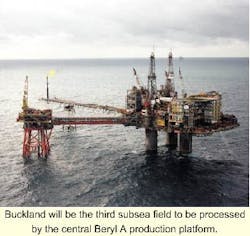
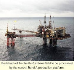
Operators re-visit subsea completions as option to costly FPSOs
Safety concerns have barred the passage of FPSOs to the Gulf of Mexico, however, in the North Sea, the key issue is economics. Falling oil prices and hapless construction delays have turned many UKCS operators off floaters and back onto subsea developments. Subsea projects have a habit of delivering oil below budget and ahead of schedule.
Buckland is a case in point. The field, in UK Northern North Sea Quadrant 9, was discovered in 1979 in 108 meters water depth through well 9/18a(N)-3A. Reserves looked respectable, but high barium levels in the formation water rendered produced water separation and disposal unavoidable. Like numerous other problematic marginal fields, it then got shelved.
The re-emergence of FPSOs this decade re-opened the debate. Operator Conoco evaluated the well test vessel Crystal Sea for a production role, with a view to piping the oil nine miles to the Mobil-operated Beryl complex. Elsewhere in the North Sea, Kerr-McGee was addressing a similar sulfate/FPSO scenario, but in this case, there was no obvious host platform to fall back on.
When Conoco sold its UKCS interest in 1997, control of Buckland, Sorby and other interests in Quadrant 9 was assumed by the Beryl partners, plus Repsol, which maintained its one-third interest in Buckland. So the field's new owners were Mobil (35%), Repsol (33.3%), Amerada Hess, and Enterprise Oil with around 14% each, and OMV with 3%.
Five-well scheme
Almost immediately, the new lineup discarded the FPSO option in favor of a five-well subsea scheme tied back to the Beryl A platform through bundled flowlines. The £160 million development plan gained government approval in May 1998, and should lead to first oil from Buckland being generated this October.
According to Hugh Thompson, Buckland team leader at Mobil North Sea, "Our new strategy has been to fast-track the project to realize its true value for the partnership as soon as possible."
However, even this new plan had to be modified following reinterpretation of a 3D seismic survey conducted over Buckland in 1997. Previous thinking had been that the field's reserves were split evenly between its north, central, and southern sections. This had inspired a solution involving two drilling centers with one producer well on each of the three field sections. The north and central parts were due to be supported by one water injector well (for pressure maintenance) while the south would have its own water injector.
But new data indicated that a larger volume of the field's reserves were in the north, while those in the south were smaller than anticipated. This led to water injection plans here being put on hold. In addition, rather than drilling a new, high cost southern producer, the partners opted to recomplete 9/19a-28, a suspended oil producer to the south-west, which was drilled as an appraisal well. The government also sanctioned this revision.
Bundle choice
Over the past three years, two other fields, Nevis South and Ness South (formerly known as Katrine), have been tied back subsea to Beryl, but in both cases through individual flowlines. Buckland represents Mobil's first encounter with a flowline bundle. The package, supplied by Rockwater, was selected following a review of 35 pipeline configurations - the main pluses cited being:
- Bundling allows the pipelines to be fabricated and pressure tested onshore
- Employing corrosion-resistant construction cuts the risk of flowline corrosion failure and subsequent hydrocarbon discharge. It also avoids use of corrosion inhibiting chemicals
- The bundle can theoretically be re-used once production has ceased, and removal should be fairly straightforward
- The bundle fabrication method allows clad pipeline materials to be used. Stainless steel cladding 2.5 mm thick is inserted into a carbon steel pipe carcass, whereas conventional flowlines have to be formed entirely from stainless steel.
Bundle composition
Buckland's bundle comprises three 8-in. diameter production flowlines, a 12-in. water injector line and a 4-in. gas lift line, plus chemical and injection controls tubing and an electric control umbilical. Much of the overtrawlable carrier pipe is 42 in. in diameter and 15 mm thick, but the diameter will be swaged down to 17-in. for the southern section of the field, with only one production flowline and one water injection line required at that point.
Under the original plan, the bundle curved to its termination at the southern drill center. Well 9/18a-28 is located beyond this point, but short-jumping will connect that well with the bundle.
"This will be one of the few bundles that Rockwater has joined out in the field in two separate parts," says Thompson. The plan is to lay first the section from the Beryl A platform to the north-central drill center, where the towhead end will be left temporarily on the seabed. The installation vessel will then return to Rockwater's base at Wick, northern Scotland to tow out the southern section to its location. This will be attached to the northern segment's towhead via latches and wires. Finally, the whole bundle will be pulled together then purged for hydrotesting. Floatover and installation was due to be completed within three weeks last month.
Completions
Semisubmersible rig JW Mclean began development drilling last October. The wells have been batch drilled and batch completed, giving significant efficiency improvements over previous subsea wells in the Beryl area, according to Thompson. The well completions are in general, simple designs configured for a 10-year production life, with minimal intervention or mechanical workovers. Production tubing, downhole completion hardware, and the Cameron christmas trees (a first use of horizontal trees by Mobil in the North Sea) are designed for sour service, with an anticipated working pressure limit of 5,000 psi.
All producer wells will have monobore completions. To mitigate scale formation, a chemical injection mandrel is being installed which will permit continuous downhole scale inhibitor injection. All completion equipment, aside from the carbon steel tubing string, is interchangeable with equipment on the production wells.
One well drilled in the northwest part of the field is effectively an appraisal well, which could lift overall reserves by several million barrels if successful. However, rig operations will be suspended to allow the bundle installation to proceed, and the well should reach total depth early this fall.
The five producer and water injector wells will have individual christmas trees completed within individual manifold guide bases. Cage-like structures will also be installed to protect against dropped objects/trawler fishing. Hydraulic power and subsea control will be provided from existing systems on Beryl A.
A high barium and strontium content in the Buckland reservoir (860 and 265 ppm, respectively) militates against use of seawater for water injection, otherwise plugged formation pores and corrosion scaling would quickly set in. Sulfate-free water is being drawn from a shallow aquifer well beneath the Beryl A platform, using a Centrilift electrical submersible pump. (ESP).
Re-injection system
This system will produce 60,000 b/d of aquifer water for reinjection (it was proven during a well test on the aquifer last year). Similar systems for water injection supply have been deployed on the nearby Harding and Gryphon fields, which are sourced from the same aquifer.
This also happens to be Mobil North Sea's first experience with downhole ESPs. Final boosting to injection pressure will come from a new water injection pump installed on the platform. The 5 MW of power required for this process will be supplied by Beryl A's turbines.
Treatment of Buckland's produced water has to be isolated from produced water from other Beryl area fields' wellstream. This necessitates use of dedicated disc stack centrifuges that generate five times the separation force of conventional hydrocyclone units, and will also maintain oil in water concentrations at future, more rigorous oil in water discharge targets.
Beryl A's existing gas lift system has enough excess capacity to supply the Buckland wells. Scale inhibitor for continuous downhole dosing of the wellbores and production lines will also be supplied from in-place facilities on the platform, up to a maximum rate of 750 bbl. Methanol only will be injected during production startup. Production flowlines will be insulated to insure acceptable process operating conditions for wax and hydrate mitigation.
Buckland's fluids will be brought via the bundle to the Beryl A processing facilities, using a dedicated production train. At peak, Beryl A will have to handle 30,000 b/d of oil, 40,000 MMcf/d of gas, and 30,000 b/d of produced water from Buckland. Two existing separators will be deployed. First stage separation will operate as a two-phase separator for oil/water and gas. Resultant liquids will then be processed in a three-phase atmospheric separator, prior to which fuel gas-fired heating will be added to facilitate treatment of produced water. This segregation is needed to avoid any chance of scale formation following commingling of Buckland and Beryl production fluids. Buckland's gas can be safely commingled in the existing compression system.
Oil will be stored and transported via tankers, while associated gas will be sent ashore via the Mobil-operated SAGE trunkline system. The current plan is to produce first oil in October, with plateau oil and gas output of 40,000 boe/d. At that stage, more than 50% of Beryl's liquid output will be coming from subsea satellite fields.

