DEEPWATER OPERATIONS: Midwater processing pipe bundle

Flow assurance remains one of the chief impediments to production from deep-water fields. As is well known, low temperatures and pressure gradients can stimulate wax and hydrate formation, putting flowlines at risk from blockages. Potential energy loss is another hazard. The situation demands unconventional measures, such as subsea separation and riser towers, but subsea separation is still largely unproven, and riser towers increase the number of complex subsea connections.
A simpler approach might be to group the flowlines carrying the produced fluids in one rigid bundle, suspended at a midwater location between a surface wellhead platform and the main production center. This would render seabed temperature and pressure variations irrelevant. But the system would need guaranteed stability to work.
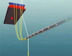
SBM (Monaco) is addressing this issue through its new Gravity Actuated Pipe (GAP) concept. This comprises a rigid section of bundled flowlines with two sets of flexible jumpers at each end. The flowlines are suspended in a horizontal position between the dry completion unit and the production platform (floating production unit) by means of two vertical sets of flexible jumpers. The bundle would be structurally supported by a continuous carrier pipe, configured to provide a neutrally buoyant bundle in its normal flow density mode. The carrier pipe would include numerous watertight compartments, each around 100 meters long, to limit buoyancy loss should perforation occur.
The carrier pipe's extremities would be connected to the two platforms by dual chains extending upward at a pre-determined angle. Clump weights would also be attached at the carrier pipe ends. The weights, acting on the angled chains, would keep the pipe carrier suitably tensioned. The tension would also maintain the bundle's hog/sag deflections within acceptable limits, should variations occur either in density of the transported fluids or the distance between the two platforms. Furthermore, the tension would serve to control lateral deflections of the bundle induced by transverse currents.
Carrier pipe
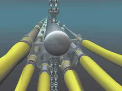
The various flowlines, situated around the carrier pipe, would be sustained by equally spaced radial supports. To accommodate their varying thermal expansion, the flowlines would be firmly secured at the center of the bundle, but merely guided into the other radial supports. Due to this free-sliding capability, the clump weight action would only impact the structural member.
SBM has had positive responses to the concept from operators of potential deepwater field developments. Studies suggest that the GAP concept could be fabricated and installed using local capability in such areas as West Africa and Brazil.
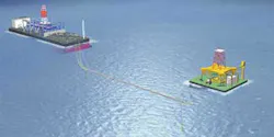
Engineering work to date has been based on a GAP connected to a spread-moored vessel and a dry completion unit (DCU), or between a turret-moored floating production, storage, and offloading (FPSO) unit and DCU. The latter scenario, said to involve more complex design requirements, was recently applied to a theoretical field development in the Campos Basin. In this case, the turret-moored FPSO is situated in 940 meters water depth, while the DCU - which could be a SPAR, semisubmersible production unit, or tension leg wellhead platform - is installed 2.7 km distant, in 870 meters water depth. The fluid transfer system consists of the following:
Two 10-in. production multiphase flowlines: one 6-in. production test multiphase line; one 8-in. gas lift line; one 4-in. gas lift test line; and one 8-in. water injection line.
Configurations
The 2,320-meter-long bundle is close to horizontal at a nominal water depth of 200 meters. The pipe bundle operating fluid weight of 108 kg/meter results in a neutrally buoyant configuration. At each bundle end, there is a clump weight with a total hung wet weight of 200 tons for the turret-moored FPSO. The bundle hangs from the FPSO and the DCU with an overall inclination of 45 degrees from horizontal, in the nominal case - defined as follows: FPSO-DCU distance is 2.7 km, with no environmental loading and a fluid weight average of 108 kg/meter. In total, there are four load cases to be analyzed for the GAP:
- Total fluid weight nominal: 108 kg/meter
- Total fluid weight maximum: 140 kg/meter
- Total fluid weight minimum: 50 kg/meter
- Accidental flooded case: 200 kg/meter.
The governing parameter for the sizing is the wide range of the operating fluid masses (50-140 kg/meters), while attempting to remain in a Sag/Hog motion in the range +/- 125 meters. Another constraint is the need to minimize the pipe bundle current excursion to avoid hitting the nearby FPSO mooring legs. To accommodate this, the connecting chains were placed at 45 degrees from horizontal and 200-ton weights were used for the turret-moored FPSO. Smaller weights can be used for a spread-moored FPSO, SBM claims. Also, the turret-moored FPSO could take smaller weights if the turret was designed to accept the GAP system at the project's outset.
Testing
SBM performed static and dynamic behavior analysis using the Orcaflex program, which provides static and time domain numerical simulations. Factors analyzed included bend stiffness of the individual bundled flowlines and carrier pipe, and hydrodynamic characteristics (total mass, drag and added mass).
To determine the influence of the GAP system on the static positions of the FPSO and DCU (in this case, a TLP), their anchoring horizontal stiffness were modeled using, in the FPSO's case, Orcaflex buoy elements and in the TLP's case, link elements. Based on the load-excursion curves provided, the horizontal stiffness of the FPSO anchoring was close to 8 tons/meter. Based on a global pre-tension of 3,200 tons for tendons 1,000 meters long, the TLP's horizontal stiffness was also estimated to be linear, approximating 3.2 tons/meter.
A preliminary and coarse vortex-induced vibration analysis has also been conducted, which demonstrates that the carrier pipe is not VIV (vortex-induced vibration)-sensitive. A key advantage of the bundle cross-section is its non-symmetry. This factor should reduce locking of the cross-flow oscillations (upper and lower vortices will not have the same strength and frequency).
Following these analyses, SBM concluded that any number of pipes could be assembled in one GAP bundle. Large density fluctuations could be tolerated in individual pipes, and the bundle could also tolerate pipe differential thermal growth. There also appeared to be no limitations on diameter.
Fabrication techniques
SBM suggests two approaches for construction of the GAP. The bundle could either be fabricated at a seaside location followed by slow launch into the sea. Alternatively, the bundle could be transported in sections to a barge, and assembled, and launched from the vessel in protected waters near shore.
The onshore procedure assumes that the yard is situated in a bayfront location protected from waves, swell and current, and flat enough to allow roll-out of 2.3 km long flowlines. Following launching and ballasting, the GAP would be towed to the site and installed in between the DCU and FPSO.
Offshore fabrication would involve use of a 150-meter-long, flat top barge equipped with side ramp and stinger for launching the bundle into the sea.
A near-surface tow has been assumed, with the pipes filled with seawater to give the GAP the correct net buoyancy to avoid the need for flooding operations offshore. Two 110-ton bollard pull tugs or anchor-handling vessels would be sufficient for the tow. On arrival at the field location, following maneuvering of the GAP, chains and clump weights would be attached to the two floaters, followed by the flexible jumpers. Lead and trail towheads are fitted on the GAP carrier pipe.
The towing vessels would carry load cells to monitor tension in the towing lines. Both vessels increase their pull until minimum towing tension is attained. The lead vessel slowly increases power until it reaches the specified towing speed. Tow tension and offsets will have to be strictly monitored. If strong lateral currents form, tow tension may need to be increased or the pipe heading may have to be altered in order to reduce lateral loads/drag.
In conclusion, SBM claims the GAP has demonstrated its viability through the studies performed so far. It also offers the following advantages:
- Any number of pipes can be assembled in one bundle configuration
- Bundle configuration tolerates large density fluctuations in individual pipes
- Bundle tolerates pipe differential thermal growth
- Pipes can be insulated to prevent heat loss.
- No diameter limitations
- Bundle is easy to tow, install and subsequently inspect
- No practical limit on length, fatigue resistant, with all components proven.
Further design of the GAP needs to be undertaken in cooperation with potential clients. All aspects of field architecture must be addressed to achieve an optimum design, starting from parametric studies through the optimization phases, which will include the preferred field layout. In time, the GAP could also be adapted to transfer stabilized crude between an FPSO and an offloading terminal, or to transfer large quantities of gas or LNG between two floating units.