Slanted column structures minimize vortex induced motions
Cuneyt Capanoglu, Robert W. Copple - International Design, Engineering and Analysis Services (I.D.E.A.S.) Inc.
The Gulf of Mexico is unique because very high nonstorm related currents extending hundreds of feet below the sea surface often cause Vortex Induced Motions (VIM) and disrupt operations. These currents, known as loop currents, are a concern for many drilling and production facilities in deepwater areas of the GoM. The Slanted Column Offshore Structure (SCOS) configuration not only minimizes the effect of these loop currents but also enables cost effective construction and installation. Model basin towing test results reported in a recent ISOPE paper (Capanoglu & Copple, 2006) indicates that the vortices shed due to loop current on slanted columns are localized, thereby significantly reducing overall motions.
Minimizing VIM
A structure subjected to wind or current flow will experience oscillating forces transverse to the direction of flow due to the shedding of vortices. If the structure responds to these excitation forces, vortex induced motions can occur. It is desirable to minimize the occurrence of large, steady-state oscillations known as “lock-in” between the natural frequency of the structure and the vortex shedding frequency. Engineers have attempted to minimize VIM by introducing suppression devices, such as the helical strakes, to avoid “lock-in”.
Effectiveness of suppression devices depends on many parameters. Typically, spar hulls have strakes that spiral downward at a 1:5 pitch (i.e., one complete spiral at five times the hull diameter), and the spiral extends outward 10% to 14% of the hull diameter. However, effectiveness of such strakes is not fully achieved due to pipes on the outside of the hull and the mooring chains going through the openings on these strakes. These helical strakes not only add construction cost and transportation complications but also cause an increase in overall current loading on the structure, thereby requiring an increase in station-keeping system capacity.
Analytical studies performed by the authors on slanted columns indicated that “lock-in” would occur only for a limited column length. This premise was supported by work performed by others over an extended period. Theoretical work on uniform cylindrical shells subjected to a sheared flow (Vandiver, 1985) indicated that one of the well separated natural frequencies of the cylinder could lock-in with one mode. Although the response amplitude would be much smaller than that for a uniform flow, it would be difficult to estimate the response amplitude or the dominant mode. Further comprehensive work on application of sheared flow to uniform cylinders (Humphries and Walker, 1986) and uniform flow on stepped and tapered cylinders as well as sheared flow on uniform cylinders (Walker and King, 1988) indicated that (1) the amplitude of oscillation of a uniform circular cylinder subjected to a sheared flow is smaller than the amplitude for a uniform flow, and (2) the amplitude of oscillation of a tapered circular cylinder subjected to a uniform flow will be the same with that of a uniform cylinder subjected to a sheared flow when the gradient of the taper and the shear flow profile are the same.
These conclusions can be explained by stating that only a segment of the cylinder subjected to a sheared flow will lock in to a specific velocity. Work performed on stepped cylinders subjected to uniform flow also shows that the response amplitudes are smaller than those for uniform cylinders. Since the response amplitude peaks can be related to specific diameters, overall reduction of response correlates to the effective lengths of the cylinder affected by vortices along the cylinder. The authors (Walker and King, 1988) conclude that tapered cylinders will exhibit lock-in vibrations for a wide range of uniform velocities, indicating that there will be one particular diameter on the taper with a limited effective length that will be excited by one of the velocities within the test range.
Facility selection
Based on the foregoing, it was determined that an offshore drilling and production facility with multiple slanted columns would minimize VIM. To validate this premise, a desirable multi-column configuration was developed and a scale model tested at Offshore Model Basin (OMB) in Escondido, California.
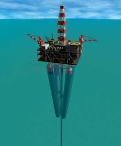
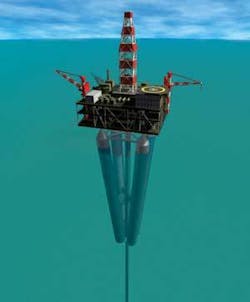
Primary requirements for the SCOS configuration were that it could operate in 1,000 to 2,500 m of water, have adequate deck payload capacity to accommodate drilling and production equipment, and have the capacity to process 40,000 b/d of oil and 50 MMscf/d of gas from four or five wells. The basic components of SCOS are:
- A deck structure with a 50-m x 50-m surface area
- A hull made of four slanted, 110-m long, 7.62-m diameter ring- and stringer-stiffened columns, and 6.1-m diameter center well
- A restraining leg made up of four 762-mm diameter commingled tubulars extending from keel to the seafloor.
This structure, illustrated above, is intended to support 4,100-metric ton deck payload. Based on conceptual design results, it is estimated that the hull structure and the restraining leg structural steel requirements are 3,500 metric tons and 1,230 metric tons, respectively, and the hull displaces 16,100 metric tons. Pertinent data on this particular SCOS is shown on Table 1.
| Components | Weight/force (metric tonne) |
|---|---|
| (A) TOPSIDE | |
| Deck Payload | 4,100 |
| Deck Steel | 1,230 |
| Sub-Total | 5,330 |
| (B) HULL | |
| Steel | 3,500 |
| Appurtenances | 300 |
| Ballast | 4,970 |
| Sub-Total | 8,770 |
| (C) RESTRAINING SYSTEM | |
| Steel | 1,220 |
| Pretension at Seafloor | 780 |
| Sub-Total Pt | 2,000 |
| (A)+(B)+(C)=Displacement | 16,100 |
The model basin program objective was limited to assess the VIM performance of the SCOS. To study the effect of slanting cylindrical columns, it also was necessary to study the unit with the cylindrical columns parallel to the centerwell. To achieve this, a 1:63 scale model SCOS hull was constructed using PVC pipes and steel plates. The steel plates were machined to accommodate spreading of the cylindrical column attachment points and achieve the desirable slanting. The PVC pipes were made watertight by plugging both ends. Considering the need for additional data, an alternative configuration consisting of three cylindrical columns around a centerwell also was constructed.
Test results
The test results can be summarized as follows: The three-column SCOS is most susceptible to VIM when the current is perpendicular to a line connecting the two columns (i.e., 180-degree orientation). Sway motions with the columns close together and parallel to each other at 3 and 4.5 knots were 61 ft and 95 ft, respectively. When the columns were slanted at 6.2 degrees the sway motions at 3 and 4.5 knots were 18 ft and 22 ft, respectively. The four column SCOS is also most susceptible to VIM in the same orientation (i.e., 0-degree orientation). The sway motions with the columns close together and parallel to each other at 3 and 5 knot towing speeds were 39 ft and 50 ft, respectively. When the columns were slanted at 8 degrees, the sway motions at 3 and 5 knot towing speeds were 8 ft and 11 ft, respectively. The three- and four-column SCOS sway amplitudes as a function of towing speed are illustrated on Figures 1 and 2.
null
Although the model basin towing tests were limited, the authors believe these tests validated the premise that slanting the columns limits the “lock-in” phenomenon to short segments of the columns and that accounts for the dramatic reduction of VIM due to current.


