Study examines causes of slugging in subsea flowline
L. Wang
L. A. Dykhno
G. J. Zabaras
Z. Huo
Shell Global Solutions (US) Inc.
C. R. Holloway
N. B. Dee
W. Nisbet Jr.
Shell Exploration & Production Co.
One Shellsubsea tieback in the deepwater GoM has experienced numerous production issues such as wax, asphaltenes, scale, emulsions, and sand production. In addition to various flow assurance issues related to the produced fluids, unexpected unstable oscillating flow has also been observed after well stimulation jobs, which nevertheless boosted the wells production significantly.
The observed unstable flow (slugging) was characterized by high pressure fluctuations and significant water cut variations at topsides, which leads to platform trips and occasional shutdowns.
In turn, the gas surge due to slugging is problematic to production because it can lead to topsides trips and production constraints due to limited gas compression capability of the platform. It was noted that a significant increase in liquid production rate did not reduce the slugging tendency. Filter sample analysis from the topsides free water knockout identified a highly viscous emulsion/sludge coming from the subsea system. The emulsion/sludge may be generated by subsea choking or well fluid incompatibility. The combination with other flow assurance issues experienced during production has made the slugging behavior difficult to distinguish and to suggest mitigation options.
To better understand this phenomenon and optimize the production, it is critical to understand the slugging patterns and to identify the root cause of the unstable flow. The commercial transient multiphase flow simulation tool OLGA was used to predict the slugging tendency. Several mechanisms that could provide reasonable explanation for the observed unstable flow were proposed and investigated. In particular, the mechanisms of riser-induced severe slugging, terrain-induced slugging, and growing slugs were studied. Other possible explanations of the slugging related to flowline topography, organic solid deposition and emulsion/sludge were also investigated. Comparisons between the simulation results and the available field data allowed for validation of various slugging mechanisms, identifying the most probable root cause of the observed slugging, and recommending mitigation strategies.
Field description
The subsea tieback consists of foursubsea wells: namely A1, A2, A3, and A4 at a water depth around 4,000 ft. The subsea field is tied back to the host platform through an 8 x 12-in. pipe-in-pipe flowline. The flowline is about 18 miles long, with mostly uphill topography from the subsea manifold up to the riser base. The produced oil API gravity is 27-28°. The produced fluid GOR (gas-to-oil ratio) is 800-900 scf/stb (standard cubic feet per stock tank barrel) and the associated water cut varies from 0% to 70% for each well. Note that A1, A2, and A3 wells produced a significant amount of water.
Flow assurance issues
As noted, the field has experienced numerous flow assurance issues such as wax deposition in the riser at low flow rates, asphaltene solids collected during well interventions, and scale appearance once the scale inhibition was turned off. Some other field observations include the inability to reach the target blowdown pressure and solids production during restart indicate that solid deposition or even plug may exist near the riser base. The plug was speculated to be either wax or asphaltenes. Finally yet importantly, simulation with clean pipes shows about 30% less pressure drop compared against the field data.
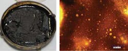
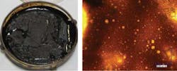
After a planned shutdown, operations discovered that the pressure communication between the manifold and topsides was limited in the flowline. A large number of liquid and filter samples were taken at different times during system restart. The liquid samples were later found to be emulsions with different water cuts. Such emulsions have the viscosity up to 1000 cP at low shear conditions (i.e. shear rate about 1 sec-1). The filter samples were initially thought to be asphaltenes deposits. However, asphaltenes analysis (IP 143) showed that the "solid" only had ~9% asphaltenes content, comparable to the oil samples. Further study by microscope showed that those "solids" are also emulsions with significantly higher viscosity – as high as 1.5x10⁶ cP at low shear rates.
Displaying 1/2 Page 1,2, Next>
View Article as Single page


