Study examines causes of slugging in subsea flowline
L. Wang
L. A. Dykhno
G. J. Zabaras
Z. Huo
Shell Global Solutions (US) Inc.
C. R. Holloway
N. B. Dee
W. Nisbet Jr.
Shell Exploration & Production Co.
One Shellsubsea tieback in the deepwater GoM has experienced numerous production issues such as wax, asphaltenes, scale, emulsions, and sand production. In addition to various flow assurance issues related to the produced fluids, unexpected unstable oscillating flow has also been observed after well stimulation jobs, which nevertheless boosted the wells production significantly.
The observed unstable flow (slugging) was characterized by high pressure fluctuations and significant water cut variations at topsides, which leads to platform trips and occasional shutdowns.
In turn, the gas surge due to slugging is problematic to production because it can lead to topsides trips and production constraints due to limited gas compression capability of the platform. It was noted that a significant increase in liquid production rate did not reduce the slugging tendency. Filter sample analysis from the topsides free water knockout identified a highly viscous emulsion/sludge coming from the subsea system. The emulsion/sludge may be generated by subsea choking or well fluid incompatibility. The combination with other flow assurance issues experienced during production has made the slugging behavior difficult to distinguish and to suggest mitigation options.
To better understand this phenomenon and optimize the production, it is critical to understand the slugging patterns and to identify the root cause of the unstable flow. The commercial transient multiphase flow simulation tool OLGA was used to predict the slugging tendency. Several mechanisms that could provide reasonable explanation for the observed unstable flow were proposed and investigated. In particular, the mechanisms of riser-induced severe slugging, terrain-induced slugging, and growing slugs were studied. Other possible explanations of the slugging related to flowline topography, organic solid deposition and emulsion/sludge were also investigated. Comparisons between the simulation results and the available field data allowed for validation of various slugging mechanisms, identifying the most probable root cause of the observed slugging, and recommending mitigation strategies.
Field description
The subsea tieback consists of foursubsea wells: namely A1, A2, A3, and A4 at a water depth around 4,000 ft. The subsea field is tied back to the host platform through an 8 x 12-in. pipe-in-pipe flowline. The flowline is about 18 miles long, with mostly uphill topography from the subsea manifold up to the riser base. The produced oil API gravity is 27-28°. The produced fluid GOR (gas-to-oil ratio) is 800-900 scf/stb (standard cubic feet per stock tank barrel) and the associated water cut varies from 0% to 70% for each well. Note that A1, A2, and A3 wells produced a significant amount of water.
Flow assurance issues
As noted, the field has experienced numerous flow assurance issues such as wax deposition in the riser at low flow rates, asphaltene solids collected during well interventions, and scale appearance once the scale inhibition was turned off. Some other field observations include the inability to reach the target blowdown pressure and solids production during restart indicate that solid deposition or even plug may exist near the riser base. The plug was speculated to be either wax or asphaltenes. Finally yet importantly, simulation with clean pipes shows about 30% less pressure drop compared against the field data.
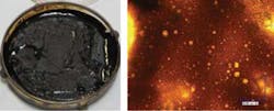
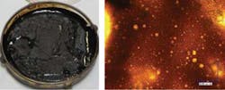
After a planned shutdown, operations discovered that the pressure communication between the manifold and topsides was limited in the flowline. A large number of liquid and filter samples were taken at different times during system restart. The liquid samples were later found to be emulsions with different water cuts. Such emulsions have the viscosity up to 1000 cP at low shear conditions (i.e. shear rate about 1 sec-1). The filter samples were initially thought to be asphaltenes deposits. However, asphaltenes analysis (IP 143) showed that the "solid" only had ~9% asphaltenes content, comparable to the oil samples. Further study by microscope showed that those "solids" are also emulsions with significantly higher viscosity – as high as 1.5x10⁶ cP at low shear rates.
Field observation
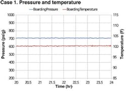
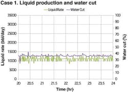
In addition to aforementioned flow assurance issues, unexpected unstable flow was observed after well stimulation jobs. The observed unstable flow (slugging) was characterized by very high pressure fluctuations and significant water cut variations at topsides, which leads to platform trips and occasional shutdowns. The field production history and flow conditions at the riser outlet are summarized in chronological order in the table. The A1 well stimulation job was performed between Case 1 and Case 2. The A2 well stimulation job was performed between Case 2 and Case 3. The unstable flow was observed right after the well stimulation jobs. The slugging frequency and slug sizes were estimated based on the field data.
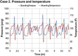
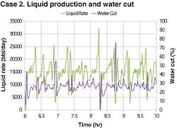
Hydrodynamic slug flow was observed for cases 1, 5, and 6, where the pressure, temperature, liquid rate, and water cut fluctuations are very small (less than 5% from the average). The slugging frequency for hydrodynamic slugs is about one slug per 3-5 minutes and the slug size is about 2-3 bbls per slug. On the other hand, unstable flow (observed for cases 2, 3, and 4) was characterized by high pressure fluctuation at upstream of the boarding choke, significant temperature drop due to gas expansion in the riser and large fluctuations in liquid rate and water cut. The observed slugging frequency is about one slug per 15-20 minutes and the slug size is about 10-15 bbls per slug.
Analysis approach
OLGA (version 5.3.2.2) was used to investigate the slugging tendency and validate possible slugging mechanisms of the system. The slug-tracking option was activated with the default delay constant of 150. The intent of using OLGA transient simulations was to capture the slugging tendency for each mechanism proposed. The explanations for the observations are mainly based on simulations and comparisons against the field data. Past experience indicates that slugging predictions made through the use of a multi-phase flow simulator (such as OLGA) are at the limit of the current understanding and modeling capability. However, this validated multi-phase flow tool can properly capture the slugging tendency and the sensitivities to various operating conditions.
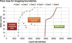
A flow regime map was first developed using OLGA to identify the slugging boundaries of the system at the riser outlet. The flow map is presented as a function of total liquid rate and water cut (assuming a constant GOR of 900 scf/stb) for easier comparisons against the field data. Then the developed flow map was used to validate various mechanisms proposed to explain the slugging patterns observed in this field. Other possible mechanisms were also validated through OLGA transient simulations, such as severe slugging due to downward section upstream of the riser base, possible slugging due to choking effect by organic solid deposition, and emulsion/sludge-induced slugging by highly viscous emulsion/sludge in the subsea system.
Flow regime map
Three distinctive flow regimes were identified in the flow regime map developed through OLGA: the unstable oscillating flow, hydrodynamic slug flow, and stable flow. The unstable oscillating flow is observed at low liquid rates and high water cuts. At low flow rates, the liquid falls back in the riser and the pressure drop of the system is dominated by the hydrostatic pressure loss. Significant pressure fluctuations are observed but the oscillation frequency is much lower than hydrodynamic slugging. The hydrodynamic slugging flow regime is encountered at moderate flow rates and at all water cuts. The stable flow regime is encountered at high flow rates.
The six production cases retrieved from the field data were superimposed on the flow regime map. The operating conditions for all of the cases except case 6 fall into hydrodynamic slug flow regime. However, only cases 1 and 5 agree well with the field observation. Cases 2, 3, and 4, exhibit much worse slugging behaviors that cannot be explained with the flow map. Therefore, a few possible mechanisms /hypothesis for the slugging occurrence observed in cases 2, 3, and 4 were proposed.
Severe slugging. The necessary conditions for the severe slugging to occur include 1. A downward flowline section at riser base with stratified or annular flow; 2. Unstable flow in the riser, and 3. Liquid blockage at the riser base. For cases 2-4, those conditions are not fully satisfied and the observed unstable flow does not fall into one of the severe slugging types. For example, the flowline topography does not have downward section at the riser base and hydrodynamic slug flow is predicted. In addition, unstable flow is unlikely to exist in the riser due to moderate flow rates (even up to 18,000 b/d). Field data also show that there was no production starvation as seen for most severe slugging cases. Also, slug sizes are about 10-15 bbls/slug (less than 10% of the total riser volume), which are much smaller compared to the slug sizes during severe slugging.
Terrain-induced slugging. This is similar to the severe slugging in that liquid accumulates at low dips in the flowline instead of the riser base, as seen in the severe slugging. The liquid builds up at the low spots in the flowline and eventually gets swept out as slugs. The terrain slugs tend to occur at relatively low flow rates. The terrain-induced slugging is unlikely because the flowline shows no significant low spots and the flow rates are moderate.
Growing slugs. These can occur when the liquid/gas interface for stratified flow is still stable with respect to small disturbances. The initiated slugs will be stable if the liquid holdup for the stratified flow regime is larger than the liquid holdup for the hydrodynamic slug flow regime. The growing slugs occur in the transition zone of stratified flow and hydrodynamic slug flow. Cases 2-4 have moderate flow rates and hydrodynamic slugging is predicted in the flowline at the riser base. Therefore, the slugging pattern observed in the field is unlikely due to the mechanism of the growing slugs.
Low dip at the riser base. Low dips may be generated along the flowline due to unequal settling in the mud more than 10 after the flowline was installed. In this case, a low spot just upstream of the riser base was assumed, which may lead to terrain/severe type of slugging as observed in the field. However, the OLGA simulation results did suggest that the low dip could introduce the terrain/severe slugging at topsides, mainly due to the high production rate of over 16,000 b/d. The predicted pressure, temperature, and water cut variations do not agree with the field observation either. In addition, the predicted manifold pressure is about 20% lower than the field data. With all the disagreements presented above, the hypothesis of low dip induced slugging is not valid to explain the slugging behavior observed in the field.
Choking effect. The field has experienced various solid depositions, including but not limited to wax and asphaltenes. Other field observations such as the inability to reach the target blowdown pressure, solid production during restart, and limited pressure communication between the manifold and topsides also support the hypothesis that solid deposition or even plug may exist in the flowline/riser system. The deposition/plug restricts the flow like a choke. Choked flow (slugging) could be developed due to this choking effect. The solid deposition was modeled in OLGA as a choke with a 1-in. opening. The size of the restriction was determined in order to match the amplitude of the boarding pressure fluctuations observed. The choking effect was also investigated with sensitivity to the plug locations. An OLGA simulation showed significantly smaller water cut and liquid rate fluctuations. The predicted manifold pressure is about 20% higher than the field observation. Therefore, it is unlikely that the hypothesis of obstruction in the riser or in the flowline leads to the slugging patterns observed.
Emulsion/sludge-induced slugging. The factors that supported the existence of the heavy emulsion/sludge in the system include:
- "Solid" samples collected from the free water knockout during system restart showed high viscosity emulsions as per filer sample analysis
- Recent well stimulation jobs may have introduced emulsified agents
- Reducing the total rate by shutting in A3 well helped reduce/eliminate slugging
- There is a known sand issue from A1 prior to A1 failure, which could intensify the emulsion in the system
- Simulation with clean pipe predicted a 30% less pressure compared against the field data
- A blowdown exercise indicated that packing more gas prior to blowdown makes blowdown more effective.
The emulsion/sludge may be generated by subsea choking or incompatibility of the fluids from different wells. The hypothesis of emulsion/sludge-induced slugging is that the subsea system generated emulsion/sludge exists as the fourth phase in addition to the oil/water/gas three-phase mixture. The residence time is too short for the viscous emulsion/sludge to dissipate in the flowline and riser. The emulsion or sludge was periodically generated in the subsea system and the "immiscible" emulsion/sludge flowed with the oil/water/gas mixture, creating slugs similar to the slugging patterns caused by the pigging operations.
To validate the hypothesis through transient simulations, the emulsion/sludge was modeled as a series of pigs with smaller diameter than the pipe ID. The pigs were launched from the manifold with a frequency of one pig per hour to match the slugging frequency observed in the field. The energy calculation was turned off to stabilize the OLGA simulations (therefore no temperature comparison). The simulation predictions for liquid rate, water cut, and pressure fluctuations at the riser outlet show good qualitative agreement with the field data. The predicted manifold pressure and slug size (15-20 barrels per slug) also showed good agreement with field data. The mechanism of emulsion/sludge-induced slugging seemed to reasonably explain the slugging behavior.
The origin of the emulsion/sludge may be due to subsea choking and/or incompatibility of the produced fluids from different wells. In addition, the recent well stimulation jobs may have introduced emulsified agents. Other solids, such as wax, sand, scale and asphaltenes that have been experienced in the subsea system also tend to intensify and complicate the emulsion/sludge issue.
Findings
Comparisons between the simulation results and the field data show that the proposed emulsion/sludge-induced slugging mechanism can reasonably explain the observed slugging behavior. The emulsion/sludge may be generated periodically in the system, which can develop the observed slugging patterns. The "immiscible" emulsion/sludge flows with the oil/water/gas mixture and creates slugs similar to some pigging devices.
Mitigation strategy
The following slugging prevention and mitigation strategies were proposed with an emphasis on reducing the amount of emulsion/sludge in the system.
With regard to emulsion/sludge prevention and mitigation:
- Actively monitor the wells' production. Produce the wells with less emulsions first and gradually produce the wells that may have emulsion issues.
- Inject demulsifier chemical upstream of the separator to improve separation.
Topsides choking should be used with care because it will only be effective when flow instability is low-flow driven – for example, when flow rates are lower than 10,000 b/d with high water cuts of 60-70%. If slugging was observed at high flow rates where hydrodynamic slugging is expected, topsides choking may not be effective and it may even worsen the slugging issue due to significant pressure build-up behind the liquid slugs.
Acknowledgment
Based on a paper presented at theDeep Offshore Technology International Conference & Exhibition, held at the Woodlands Waterway Marriot Hotel & Convention Center, Oct. 22-24, 2013.
