WELL CONTROL TECHNOLOGY Case history of Timbalier blowout shows necessity of capping while burning

Surge operations without a safety valve leads to blowout; on-site management failure complicates emergency response
Larry H. Flak
Wright Boots & CootsMartin J. Kelly
James Tuppen
Boots & Coots
The S/P PP 192, No. 250 well was drilled originally in 1968 in the Timbalier Bay Field in south Louisiana, near the open US Gulf of Mexico. The blowout occurred during workover operations on 29 September 1992. It was capped and killed on 9 October 1992, 10 days after control efforts began. An estimated 9,500 bbl of oil were released. Most of that oil was burned off by well ignition. An account of this event can now be published, since litigation resulting from the incident and its pollution was recently concluded.
Blowout conditions
The blowout took place from perforations at the 8,802-8,830-ft depth interval in an oil sand. Flow was up 2-7/8-in. tubing to the surface - there was no annular flow because of an effective packer. The flow rate was initially 1,400 b/d, exiting at the surface from a chicksan elbow pointed out the V-door. There was no surface safety valve in the tubing string, and blind rams had been closed in an attempt to shut in surface flow, which resulted in splitting the tubing within the blowout preventers (BOP).
A significant blowout and marine oil spill was the result. Early response blowout specialists were mobilized, as were spill responders and the US Coast Guard. The first actions included site inspection by specialists, spill containment, source control plan formulation, and movement onto the scene of firefighting equipment, including a work barge and derrick barge.
Plans were made to mobilize firefighting equipment to protect blowout responders from natural well ignition. Well ignition was of high risk from low water cut and light oil, and flammable vapor concentrations were present in several areas downwind from the flow and in the barge keyway.
Booms were arranged downwind and down current to collect spilled oil. Unfortunately, crude attempts by well site personnel to contain oil with tarps concentrated flammable vapors on the barge and did little to mitigate pollution. Ultimately, this caused well ignition.
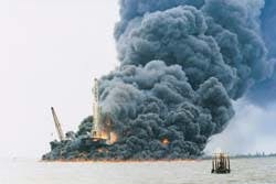
The oil is burned off soon after well ignition. Smoke is generated from the oil stored on the rig and behind the pollution booms.
Source control
The initial source control plan was as follows:- Move in the firefighting barge in an upwind direction (10% lower explosive limit or LEL) opposite the barge keyway.
- Carefully inspect for ignition hazards (engines, batteries, poorly grounded areas) and eliminate these ignition sources and define areas at the LEL on the rig.
- Clear away most of the tarps and rig floor wind wall panels to get better ventilation.
- Work only in upwind ventilated areas at LEL under direct supervision by blowout
- specialists.
- Perform only one operation at a time under direct supervision of the lead blowout specialist.
- Work within sight and under cover of water monitors at all times.
- Use water monitors to rain or mist water on personnel during work activity.
- Do not use a concentrated stream of water from the monitors as this can lead to ignition (mechanical impact, electrical grounding, or drawing air into vapor saturated areas).
- Do not allow explosive vapors to fill containers or quarters as this can make a bomb.
- Determine control options based on complications posed by blind ram closure splitting the tubing.
Blowout cause
Prior to losing control, Well No. 250 was re-entered and deepened for re-completion. Problems with corrosion of production casing and tubing were encountered. The holed 7-in. casing at 2,689 ft could only be squeezed to 350 psi.
The operator elected to proceed with completion operations and perforated the well for production at the 8,802-8,830 ft depth interval. A back surge tool was run with a packer set at 8,766 ft. The surface safety valve was available for 8RD tubing, but would not fit the PH6 tubing string without an available cross-over.
The combined length of the safety valve and crossover could not be handled above the elevators because of short elevator links. Supervisory personnel at the site decided to proceed with surge operations without a safety valve, depending on a single barrier - the upper surge control valve.
On 30 September, the well surged. The upper surge control valve failed, and the well came in. Attempts to install a pump-in line on the chicksan elbow were delayed by a winch problem. Installation became impossible later as the flow increased. In a futile attempt to shut off flow, the blind rams were closed on the 2-7/8-in. tubing.
Analysis
As is common in most blowouts, more than one thing fails. Murphy's Law and the Domino Effect prevail. The basic failure was attempting a back surge operation with only one pressure barrier, the upper surge control valve.
The pump-in line was the planned backup pressure barrier, but because of winch problems there was an installation delay. This re-enforces the need for a surface safety valve which could have been easily installed below the elevators (at the top of the test string, approximately 10 ft above the rotary).
All of the equipment for this safer hook-up was present on the rig when the blowout occurred. Finally. it is questionable if this well was suitable for re-completion given the bad casing at only 2,689 ft. Any failure of the packer or tubing would have caused a shallow underground blowout and possible worse case surface broach.
Other complications
Closing the blind rams on the 2-7/8-in. tubing complicated subsequent control operations. Blowout specialists commonly see this problem as operator and rig personnel panic in employing any means to control the well flow. Flat face blind rams only split tubing and do not greatly impact flow rates. Split tubing must then be isolated or cut out of the way to control a blowout.
Trapping oil on the rig to mitigate pollution is not possible when the well is flowing at such great rates. This leads to greater ignition risk and worse consequences if ignition occurs. It is far better to allow oil to disperse in the wind. If this is not possible, the operator must consider voluntary well ignition.
The cost of this workover barge rig was far less than the cost of pollution clean-up. The rig was valued at less than $500.000. The cost of pollution clean-up was in the millions. Voluntary ignition should had been considered, but who pays for the rig loss? Significant legal and insurance questions remain.
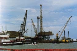
The initial control of a blowing well was set up including a pollution boom, derrick barges, and water spray.
Blowout control
The initial control plan was to achieve the following:- Clear the rig floor.
- Tie back the blocks.
- Cut-off the chicksan swivel to move the well flow to a vertical stream.
- Cap the tubing with a three-ram stack (blind, inverted pipe, and inverted slip).
- Hook up the diverter and pump-in lines, close the BOPs, and divert the flow.
- Open the lower BOP and install inverted pipe rams to isolate the split tubing from the annulus.
- Close the upper pipe rams and/or annular BOP to isolate the split tubing.
- Pump in and kill the tubing flow.
The cutter is set up to cut away the damaged tubing.
Well ignition
Work was proceeding when the well was ignited by static electricity. Investigators later determined that the non-conductive and ungrounded tarps containing oil spray were excellent points for static electricity charge build-up.
One of the tarps located below the rig floor was tied off with a rope to the lower BOP stack, just above oil trapped in the keyway. This tarp had not been removed as it was helping to screen oil away from access to fig floor. Static electrical charges had built up on this ungrounded tarp and discharged, igniting vapor forming above fresh oil pouring into the keyway.
This led to well ignition. Oil trapped in the keyway, on the rig, and behind pollution booms, then burned off. Well ignition greatly assisted cleanup efforts. Oil containment was made difficult by deteriorating weather conditions and tidal effects. Most all of the blowing oil was now burning off as was much of the oil already released.
Final control
After well ignition, no effort was made to extinguish the fire. Plans were made to cap well while the well and rig were burning. Given the tubing spilt by blind ram closure and poor casing integrity, a control plan had to keep the well contained in tubing and a bullhead kill was used for final control. The control plan was as follows:- Remove debris.
- Float the rig barge.
- Abrasive jet cut the bell nipple and tubing.
- Pull off the barge to expose the BOPs.
- Push in the work barge with fire monitors, a bulldozer, and an Athey wagon for BOP removal and capping stack installation.
- Pick up the BOPs to expose the split in the tubing and cut the tubing below the split with a pneumatic cold cutter.
- Pull off the rig BOPs with the well burning.
- Install a tubing clamp and put the tubing into tension.
- Install a wraparound tubing hanger and pack-off in the existing tubing head, hang-off the tubing, and check all lower casing seals.
- Install a three-ram capping stack over the burning tubing using the Athey wagon and a capping boom.
- Bolt up the capping stack to the tubing head flange, close the inverted slip rams, and invert the pipe rams for secondary pack-off and support. Close the blind ram to shut in flow.
- Bullhead the kill tubing.
The first actions were to stabilize the rig barge, debris removal, and pull the barge off the BOPs. Next, the fallen rig mast was cut away and removed. The barge was eventually floated after several wasted attempts to pull the barge off without pumping it out as directed by US Coast Guard.
The Coast Guard was concerned that oil trapped within the barge would be pumped out into the water. Much of the Coast Guard's actions were likened to a plumber showing up with a mop to fix a bad water leak. Unreasonable pollution concerns actually slowed control efforts. By carefully monitoring the oil level in the barge, no oil was pumped into the water when the barge was floated.
The remaining control work went as planned and without any difficulty. A heat-shielded Athey wagon and bulldozer were used to pick up the BOPs with the well burning. A pneumatic cold cutter was installed to cut the tubing below the split.
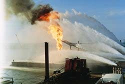
The BOPs were then pulled off the well. The well burned clean and the water spray could be used for heat shielding and not fire extinguishment. Then, the three-ram capping stack invented by Boots & Coots was installed. The blind ram was closed to shut in flow.
The well was brought under control on 9 October 1992. This was the first time an offshore well had ever been capped while burning. Significant pollution control was possible by this method, millions would have been spent in additional pollution cleanup without this achievement.
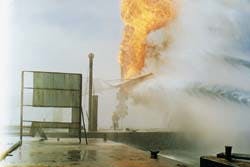
The BOP stack is removed to provide a clean burn. Water spray provides a heat shield.
Management issues
A number of management issues developed during this emergency:- Incident commander: The operator was ill-prepared for emergency response with no defined incident manger. Overall efforts suffered from lack of direction. Blowout specialists are focused on blowout control; pollution cleanup is focused only on pollution.
- The US Coast Guard is least experienced in blowout control and tends to focus solely on pollution mitigation at the cost of delaying control efforts. The operator then reacted to instead of directing operations. Management of emergency response suffered.
- Competition: Tugs, helicopters, supply boats, and basic logistical support are shared between blowout control and pollution control. If one element is needed by blowout control and pollution control, who gets it? Is it the control element that needs it the most, or the one that yells the loudest? This is not good emergency response.
- What would be more important - mopping up a few gallons of oil or stopping the release of thousands of gallons per day. Competition for resources was real and did delay blowout control operations.
- US Coast Guard: When a domestic marine blowout occurs, the US Coast Guard leads the regulatory response and has a major role in emergency management. In this case. they played a more significant role because the operator could not provide an experienced incident commander. While Coast Guard did not take over this role, they did impact decision-making greatly, and not necessarily positively.
Conclusions:
- Two pressure barriers should always be in place particularly during higher risk operations such as the back surge operation done in this case.
- Re-completing a well with bad casing that is unable to withstand production shut-in pressure is a bad practice. In this case, the easy control option of dropping tubing below the BOPs and shutting the well in on the production casing with rig blind rams (rams possibly damaged by attempts to close on tubing) was eliminated by that action.
- Closing the blind rams in an attempt to shut off the flow did not work and complicated subsequent control operations. In the author's experience, closing the blind rams on pipe has never shut off a blowout and always complicated control efforts. A shear ram would have been worse because of the bad casing.
- Plans to handle possible well ignition safely during early work effort saved lives and injuries. Recently in another blowout handled by other parties, two men died, one was critically injured, and others were hospitalized in a similar blowout where these cautions were not taken.
- Operator must put a single individual in overall charge with the experience and management skills necessary to control potentially competing forces at work. If this is not done, the operator can be forced into bad plans and poor response. Planned emergency response is needed with task assignments and responsibilities defined. Document control, and financial and logistical management are required. Organized coordination meetings with field response control staff are required. Regulatory overview from the US Coast Guard must be handled in an organized fashion.
- The operator must have an Emergency Response Plan that all of the operator responders are trained in and experienced with. Emergency response should be orderly and planned.
The emergency plan must incorporate a well control incident management system.
- Operator should pre-contract with emergency responders to set contractual terms and financial issues before the emergency.
REFERENCES
Alberton, Paul Lt (jg) US Coast Guard, "Well Blowout On Inland Barge Rig, "presented and part of proceedings of IADC Well Control Conference of the Americas, Nov. 1993.
Flak, L., Kelly, M., "Blowout control: Response, intervention and management series Part 10- "Blowout surface intervention methods, "World Oil, November 1994.
Wright, I., Flak, L., "Blowout control: Response, intervention and management series, Part 12 - Incident management and critical alliances, World Oil, April 1995.
Copyright 1995 Offshore. All Rights Reserved.