Frank Hartley • Houston
Sand erosion assessment
Operating companies and asset managers are aware of the dangers of solids produced from the reservoir formation and, therefore, take proactive strategies to manage the impact of solids production and maximize productivity.
Solids production is typically episodic and can cause extreme damage almost instantaneously. Consequences include erosion of choke valves, erosion and accelerated corrosion of pipework, reduction of corrosion inhibitor performance, and filling of separators -- all resulting in reduced well productivity. Reliable instantaneous measurement of hot spots in offshore and subsea systems is of vital importance.
The high sand content of mature oil and gas producing fields is proving to be a challenge for engineers at TUV NEL Ltd.’s (NEL) erosive flow test facility, located in their Scottish headquarters.
This has led to further enquiries for a unique erosion assessment to identify and predict erosion hot spots in E&P components under erosive flow conditions.
Erosive flow loops
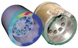
The erosion assessment analyzes both computational fluid dynamics (CFD) flow modeling and dedicated erosive flow loops. Within the loops, a variety of fluid-sand mixtures can be pumped to test production equipment such as chokes, valves, meters, well heads, piping configurations, and other components to determine their life expectancy and operational limits in erosive flow conditions.
John Peters, a recognized authority in valves and manager of NEL’s facility, says, “New wells may initially produce moderate levels of sand at start-up. Then sand production typically stabilizes at a lower level before increasing again as the well ages and the reservoir formation deteriorates. With the majority of oil and gas fields in many areas of the world, particularly in the North Sea, now reaching a mature stage, sand production levels are increasing. Operators have a choice of disposing of the sand by downhole filtration or managing the problem by selecting components that can withstand the erosive flows for known periods. These components can then be changed out during planned shutdown and maintenance periods.
“Equipment failure leading to unplanned downtime and shutdowns can cost the industry millions of dollars, while the worse-case scenario is potentially catastrophic failure leading to loss of hydrocarbons and to accidents and injuries.
“An additional factor is that operators are reluctant to invest in mature fields due to their limited life expectancy -- some majors, for example, sell off their interests to smaller operators once a field’s productivity begins to decline. If the new operators can predict erosion hot spots and control the erosion problems caused by sand, the field’s profitable life can often be extended.”
CFD erosion modeling
The majority of the test facility’s project work is from equipment manufacturers who utilize the company’s expertise in CFD erosion modeling at the design stage to predict potential areas of erosion prior to production. The prototype is then field-tested in the erosion facility to mimic operating conditions and validate the CFD model.
The test facility injects controlled amounts of sand particles into fluid flows, which then pass through the test loop components, allowing the engineers to accelerate the effects and document the results of erosion over time in the most realistic flow conditions.
By being able to precisely control the flow rates, pressure, and sand content of the fluid, virtually any condition can be simulated and predictions produced based on this data.
NEL has been involved in developing fit-for-purpose equipment and components for operation in erosive flow conditions for many years. Even with continuing development of specialist materials, such as tungsten carbides, coatings, and ceramics, all of which have a superior erosion resistance when compared with steel, the system remains only as strong as its weakest part. For example, once a coating or its substrate fails, the resistance rapidly decreases, so it is vital to be aware of a component’s operating life under different conditions.
Peters says, “Manufacturers and suppliers are able to validate the performance of their equipment prior to installation by accelerating the ageing process using the erosive flows at the facility, similar to those encountered in service. Those who can prove that their equipment has been independently tested and verified are obviously at a competitive advantage over other manufacturers.”
Improving flare gas measurements
NEL was also recently involved in assessing the implications of gas flowmeter measurement uncertainty for Shell Exploration and Production. Ultrasonic flare-gas meters were being installed on Shell’s Cormorant Alpha and North Cormorant platforms as part of an upgrade. Under normal circumstances, the flowmeter manufacturers recommend that these meters are installed with at least 20 diameters of straight pipe immediately upstream of the meter. However, this was not feasible on the two Cormorant platforms. Shell asked NEL to assess how the performance of the flowmeters would be affected if they were not installed to the manufacturer’s specification.
However, gas flaring in the UK is currently controlled by guidelines set up by the Department of Trade and Industry (DTI). These guidelines state that the oil and gas operator must demonstrate “that they have not exceeded their flare allowance” and that in order to achieve this “some form of flow metering is necessary” in production platforms and refineries. However, when flare gas flowmeters are installed, space and operational constraints often result in meters being installed in less than ideal configurations. This can lead to increased measurement uncertainty.
NEL performed the study, which entailed performing a number of CFD simulations of the flow of gas through each flare system. In the case of the Cormorant Alpha stack, the flow came from two different knock-out drums and the effect of different flow splits was also studied. The CFD simulations were used to predict the degree of swirl and velocity profile distortion at the flowmeter. From this, the response of the flowmeters in each installation was estimated. Based on this information, a correction factor was calculated to reduce any measurement bias; estimates were also made of the uncertainty associated with the uncorrected and corrected measurements. This work allowed Shell to install the two flowmeters in their planned position while increasing their confidence that both meters would meet their uncertainty requirements.
With the EU Emissions Trading Scheme now coming into force, there will be increased pressure on operators to demonstrate that they are measuring their emissions correctly.•
