BP leverages technology to optimize deepwater performance
David Paganie, Managing Editor
About three and a half years ago, BP launched an innovative strategy for its deepwater operations in the Gulf of Mexico. It was called “Field of the Future” (FotF). Implementation of this plan would improve document control, asset management, reservoir performance, predictive analysis, and hurricane preparedness, all through a one-touch portal driven from a remote, real-time onshore technology center.
Steve Fortune, information management director, BP Strategic Performance Unit, was brought in to lead a dedicated team to develop and to implement this integrated technology program that would fundamentally change the business. Fortune givesOffshore an inside look at the technology from the “Future.”
Virtual communication
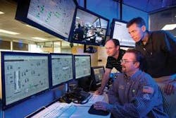
BP monitors its GoM operations through 24-hour/7-day-a-week live video feed from its onshore technology center at the Westlake office in Houston. Here, a series of control rooms or Advanced Collaborative Environments (ACEs) are set up for eight BP-operated assets:Marlin, Horn Mountain, Mad Dog, Holstein, Na Kika, Atlantis, Thunder Horse, and Pompano. The people responsible for the day-to-day operations of these offshore facilities live in this environment full time. Personnel include the operations manager, the deputy operations manager, and the production, operations, and reservoir engineers. These people can communicate visually from their office with their offshore counterparts. Operations personnel rotate from offshore through this onshore environment on a two-week offshore/two-week off/two-week onshore schedule. “This is a great development tool for operators,” Fortune says. “They get exposed and involved with many things onshore that they might not necessarily get exposed to offshore.” The onshore rotation has living accommodations at a nearby housing facility.
ACE is really about bringing the offshore and onshore teams together as one virtual team that allows BP to optimize how it produces assets, Fortune says. “We can leverage the right skill set from the onshore team in a much more real-time sense when issues come up offshore, and we can be more proactive in how the onshore team engages with the offshore team prior to these kinds of events happening.”
ACE is used by vendors. This has lead to the resolution of offshore problems, or potential problems, quicker and more efficiently, Fortune says. “In just a couple of hours, with the vendors on site, we can get about 90% of the job done, compared to what could take weeks to months to get done offshore, given that travel time is reduced and resources are used more efficiently.”
Another specialized function, automation support, has been moved to this onshore environment. The networks have been integrated at the base in Houston, allowing offshore platforms to tap into deeper pools of knowledge and experience through direct interaction with other assets, rather than having each resource limited at its base. “We’ve been able to get people off the platforms when they do not necessarily have to be out there from a safety perspective, which allows us to do things more efficiently,” Fortune says. This also helps the company leverage its resources in preparation for the next big “crew change,” he explains. In the next five to 10 years, 40% of the oil and gas industry is expected to retire.
Real-time bottleneck
Almost all voice and data communication is moving to wireless or satellite configurations. Business is conducted via mobile, mini-computer-type devices. Workers can make phone calls, email, and open documents, conducting almost all business from one small gadget. Offshore operations are not much different. People working offshore have mobile phones and/or PDAs.
This is the future, right? BP doesn’t think so, at least when considering its approach to optimizing its deepwater operations in the GoM.
In a region where technology is moving to the seafloor in increasing water depths, and where people and offshore infrastructure are at constant risk from severe weather, fast and continuous communication is critical. This is where BP recognized the limitations of satellite and the advantages of fiber optics.
The company has been de-bottlenecking a communication/data overload in its satellite services. BP has been ramping up production from its deepwater assets and has added a number of large assets over the last couple of years. To handle this huge onset of real-time sensor data, the company installed a 36-TB system. About four TB per year of new real-time data is being transmitted from BP’s deepwater facilities, Fortune says. “We’ve always faced challenges with the performance of our work management systems working offshore,” he says. “It could take anywhere from 15-30 minutes just to log in to the system.” The company also experiences delays when opening large documents, Fortune says. “We are digitizing a lot of our documentation to make it more readily accessible by anyone, anywhere in the world. Over satellite, a large document could take up to 30 minutes to open.” BP has been pushing more FotF technologies back into the ACE onshore environment - production control systems data, live video conferencing - and began standardizing work management systems, he says. “We started seeing that we had a major deficiency in bandwidth over satellite, and unless we put a fiber optic system in place to increase our bandwidth, we may not capture the full value of these FotF and information management technologies we’ve already invested in.”
The case for fiber, ACE
BP is investing $80 million in an 800-mi (1,287-km) subsea fiber-optic system to provide continuous broadband connectivity to the company’s deepwater platforms. There were seven platforms, initially. The system is designed with upgrade capacity to support 64 platforms. “Each platform gets the bandwidth equivalent of the 5,000 satellites that BP operates over today,” Fortune says.
To determine the feasibility of building this fiber-optic system, BP studied the technology together with the ACE concept, Fortune explains. “We launched a seven-month pilot on theNa Kika project. During the pilot, we started seeing some of the bottlenecks in satellite from low bandwidth; data was backing up during simultaneous video conferences from one platform.” The ACE benefit was clear, he adds. “What we saw in many cases during the pilot was the ability to respond to upsets in a much more proficient and proactive way through the multi-disciplined, collaborative environment. Having that environment in place with a mix of engineers living in it, we could quickly solve the problem and get back up and running or avoid those problems causing shutdown far more effectively than not having the environment.”
TheNa Kika pilot results indicated $7 million in value, Fortune says. With these two projects - fiber and ACE - he says the company could get a 1% improvement in operation efficiency, which was more than enough to justify moving ahead with the projects across its operations in the deepwater GoM.
The fiber loop is completely amplified and installed subsea, and the power comes from the beach, Fortune explains. “That way you’re not depending on one individual platform to provide power for the system,” he says. The other key thing is that it is a fully redundant loop. If you get a break in the cable, you can still communicate either way around the fracture, he says. If one platform is shut down by a hurricane, the other platforms will continue to have communications. If a drillship drags an anchor across one of the fiber branches and breaks it, communication would continue at the other platforms. If an asset is isolated between two breaks, it still can use the previous satellite connections as a backup to operate while connection gets re-established.
Meanwhile, “we are planning experiments around remote control operations, and we see that potential may be unlocked once fiber is in place,” Fortune says.
Design and installation
BP contracted Tyco Telecommunications to build and install the fiber-optic loop. The system is a long-haul solution, one that uses subsea amplifiers in the cable to provide the long reach for the optical signal, explains Rob Munier, managing director of global solutions, Tyco Telecommunications. The real advantage of fiber over satellite, Munier says, is its large bandwidth with a low cost and high reliability. Other communication solutions such as short-haul fiber or microwave rely on inshore platforms in a daisy chain configuration for connectivity. If you lose one of the inshore platforms, connectivity to the offshore platforms is severed.
BP’s fiber-optic system will be buried from shore out to 800 m (2,625 ft) water depth. “This is based on the assessment of risk to the cable from external aggression such as fishing or anchoring,” Munier says. Beyond 800 m (2,625 ft) of water, the risk is sufficiently reduced, he says.
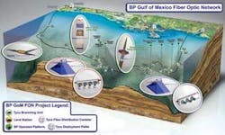
The fiber loop is a two-landing system configured in a trunk and branch. The trunk will connect to two landings onshore, one in Pascagoula, Mississippi, and the other in Freeport, Texas. Multiple branches will split off of the trunk to each of the major platforms. The initial connection will be to seven platforms. An additional 12 branching units will be installed for future expansion.
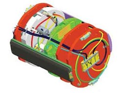
One of the things done to address this particular marketplace (offshore oil and gas), Munier explains, is to enhance the branching unit technology with multiplexing. A typical branching unit redirects fibers. For example, if there are four fibers in a trunk and one pair branch for the “local” traffic, the remaining pair goes straight along the trunk carrying the “express” traffic. That is a traditional branching unit, he says. In the case of multiplexing, instead of breaking out fibers, it breaks out a discrete optical wavelength. The advantage, Munier says, is if you are trying to connect 20 platforms with 20 branches, for example, with the traditional technology you would need 20 fiber pairs, one to break out to each branch. Right now, no cable technology supports 20 fiber pairs for this long-haul-type system. So, he says, they can instead use the large optical bandwidth in an optical fiber pair and break out one or more units of the bandwidth to each platform. This is called an optical add drop (OADM) branching unit, which is featured on the BP project.
The bandwidth capacity for the fiber system is 32 wavelengths/fiber pair. With two fiber pairs in the trunk, ultimately, there could be 64 platforms connected via 64 branches off of it. The bandwidth equivalent of one 10-GB wavelength delivered to one platform is similar to 120,000 simultaneous phone calls, Munier says.
The fiber branches will connect to a platform’s existing or newly installed fiber-optic cable riser. The new risers will be brought into a platform through an I-tube or a J-tube, which essentially is a protective steel pipe. The fiber is threaded through this pipe and is secured on the platform deck. From there, the fibers are broken out, and then a connection is made to the communications room and throughout the platform. Some of the branches will connect to existing fiber-optic umbilicals on the platforms. The connection between the branch and riser will be made on the seafloor at a deployment pallet rather than bringing the trunk all the way up the platform.
All the risers have multiple fibers in them, more fibers than are necessary just to connect to the branch. That allows connection from the primary branch platform to other platforms via a fiber distribution canister or the deployment pallet. So the highest value platforms could be connected on the branch, and the lower value structures could be sublet from the primary platforms.
Ocean Design Inc. (ODI), under contract to Tyco Telecommunications, delivered the fiber-optic wet mate connectors for the project. Supply included ODI’s mini-gateway product, which provides connectivity for the fiber distribution canisters and deployment pallets, and ODI’s rolling seal connectors, which offer wet-mateable connections for optical communication.
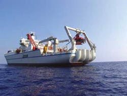
Loading of the wet plant - subsea cable, amplifiers, branches, and risers - took place at Tyco Telecom’s factory in Newington, New Hampshire. These were then loaded onto the company’s Baltimore, Maryland-basedTyco Decisive. Installation began in mid-May. The Decisive is installing the trunk, branches, and risers, and the Tyco Tenao with Triton ST 214 ROV onboard, is monitoring cable deployment, including pipeline crossing, and the installation of the risers to the platforms. The optical terminal equipment was manufactured at Tyco Telecom’s plant in Lowell, Massachusetts. It is being deployed to the cable stations at Pascagoula and Freeport, and on BP’s offshore platforms. The system is expected to be fully installed and commissioned by the end of 2007.
null
Asset management
BP is looking at predictive analytic and optimization techniques to leverage the systems it has in place, Fortune says. Through sensors and scada systems installed on virtually every component of BP’s deepwater facilities, above and below the mudline, the company can monitor everything from the wellbores, pumps, and subsea equipment, through to the risers and topside equipment.
“Most of the component designs in the industry are conservative because there is not a lot of data to go by for first of its kind equipment,” Fortune says. “For example, we put sensors on our risers to measure the movements from vibrations to understand exactly what they’re doing in high seas, during storms, etc.”
Collecting this information allows BP to analyze the system’s performance and then recalibrate the design, if necessary, based on actual performance data. “We found in a number of cases where we designed equipment for a certain design life, true performance information indicated that the design life was significantly longer,” Fortune explains. “With that, you can re-validate your design basis. That allows you to push out into deeper territories.”
BP also is looking at standardizing its real-time drilling systems within an ACE environment. “That is a big challenge for us in the GoM and across the globe,” Fortune says, “and further leverages FotF to optimize operations.”
Safety
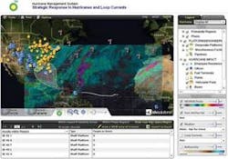
Safety systems are key components of BP’s FotF. In the aftermath of hurricanes Katrina and Rita in 2005, BP created the hurricane nanagement system (HMS) to protect its people and facilities in event of an impending threat. The front- and back-end system components, created and supplied by Microsoft and partner IDV Solutions, combine BP’s existing Microsoft SQL Server databases and Microsoft Office SharePoint Portal Server 2007 with newly installed Microsoft Virtual Earth, to enable BP to proactively monitor an incoming threat and to respond in a more effective and efficient manner before impact.
The system draws information from ESRI data, and it includes information on the weather, traffic, BP’s people, offshore platforms, pipelines, vehicles, hotel vacancies, and more, all accessible through a Web-based interface. Review and response to any offshore damage also is expedited with this system. Satellite imaging can be used to inspect the company’s platforms and rigs. “Rather than just reacting, we can see where storms are likely to travel, what assets could be impacted, what employees we have in those areas, and take action,” Fortune says.
Each piece of the FotF that we’ve been working on - hurricane management, asset management, document control, predictive analysis, reservoir optimization, etc. - could be viewed as separate projects with separate technologies, Fortune says. “When they’re looked at incrementally it would be kind of difficult to justify how some of these could fundamentally change how we operate. You have to leverage FotF and information management together to make a fundamental difference in how you run your business. And fiber optics provides the optimum network capacity to make this happen.”
