Shell-Saipem seafloor driller option on costly deepwater wells
Innovations in deepwater drilling are becom ing common place, but a radical new approach may offer the step change needed to take exploration drilling off the conti nental shelf and past the 12,000-ft water depth contour.
Shell is sponsoring the revolutionary research to move the drilling rig from the surface to the sea floor. The producer first hit on the idea in 1997 when its in-house Research and Technology "Game changer" panel laid the framework for the study.
The panel was organized to fund radical ideas in early stages before commercial value can be proven. The panel initially divided the seabed dril ling rig into two broad phases, a preliminary fea sibility study and a conceptual design. In a paper presented last march at the SPE/IADC conference in Holland, Shell author Charlie Mitchell, and co-author Giovanni Chiesa with Saipem, announced that both phases had been completed.
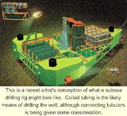
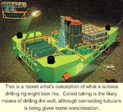
Subsea rig concept
The Phase I concept sketch was not as radical in appearance as expected. What the design team came up with was a submerged jackup-shaped rig. The vessel would be controlled using umbilicals running from a dedicated surface vessel. These umbilicals would be used to supply electrical power and control; compressed air for buoyancy and manipulaton; and possibly liquids such as cement or additives.
In the first design permutation, the rig would contain a variable buoyancy system allowing it to descend, in a controlled manner, to the seafloor. On the seabed, legs would extend to level the rig, and the buoyancy would be dumped. In soft soil areas, suction anchors or mud mats could be used to anchor the vessel.
The vessel would require a fully automated drilling package. Using some form of hydraulic derrick, the system would be similar to the modern, automated packages now in use on many deepwater vessels, except it would be marinized.
This marinization is a common theme among many of the systems considered for this vessel. The developers point out that in many cases there is no need to reinvent the wheel, when an existing system would be perfectly adequate, only that it would have to operate submerged in 12,000 ft water depth.
Pipe will be handled in single stands and stored in a rack near the centerline of the well. The bottomhole assembly will be standardized as much as possible and stored in a separate rack. Con sum ables including chemicals, cement, casing, etc. would be stored on the rig with an ROV-based system that could quickly re-supply the rig.
Fluid circulation
The mud would be circulated through a closed-loop system to keep it separate from the seawater. Cut tings would be filtered out in gravity separators and then either dumped on the seabed or returned to the surface for further processing.
The cement would be premixed on the surface using a two-part system, similar to epoxy or long-term retarders, to keep it in a liquid state at the seabed. All liquids on the rig would be contained in pressure-compensated tanks attached to the rig. These containers would be removable so they could be returned to the surface by an ROV for refilling.
System advantages
Conceived at the height of the 1997 oil boom, the initial advantage of the seabed drilling rig was to offer an option to the high cost and short supply of ultra-deepwater drilling rigs. The vessel would essentially be a marinized version of a typical surface-based drilling system. By placing it on the seabed, the Shell team identified a number of advantages over similar surface systems:
- The subsea rig apart from the length of the main control umbilical, a lift line, and the ROV umbilicals is virtually unaffected by water depth.
- Drilling from the seabed drastically reduces the time required for tripping pipe, since the pipe no longer has to travel through the water column. Assuming the average of 25 trips/well, and 8 hours to trip pipe 3,000 meters, the time savings could easily add up to several days per well.
- Along the same lines, it takes about three days to trip a riser 3,000 meters and 2-3 days to retrieve it. This function would be eliminated, as would the time it consumes.
- The seabed system would not be affected by weather conditions. While drilling might be interrupted, the rig would not be moved off station. Once the surface vessel returns and reconnects the umbilicals, drilling could continue.
- With the drillfloor located below the surface, there is no contact between personnel and the drillfloor, which is one of the most dangerous areas on any rig. Also there would be fewer crew members required to run this automated equipment.
- Circulating out gas kicks would be much safer because of the high ambient pressure at the seabed. The gas would still need to be circulated out and separated at the seabed, but the kick will not have the opportunity to expand and thus cause a blowout.
- One of the major advantages to seabed drilling is the optimum wellbore fluid pressure regime. Mud density is greater than seawater, which leads to large differential pressures at the seabed, between the riser and the surrounding seawater, and in the well. By locating the mud pumps at the seabed, the hydrostatic mud pressure in the well will be related to the ambient hydrostatic pressure at the seabed, rather than sea-level pressure.
This shift allows for more direct control of pressure at the bottom of the well using traditional methods. This one facet of the seabed system offers several advantages including reduced wellhead size, a smaller number of casing strings, the ability to drill deeper wells and improved productivity, thanks to less impairment from high differential pressures.
Phase II
With the first Phase of this study complete, Shell and Saipem decided to pursue a conceptual design with the goal of producing a rig that could drill in ultra-deepwater and under floating ice. Reliability was considered a key component to such an automated system. Redundant systems would be part of the design, as would periodic maintenance to ensure the rig would operate without interruption for a minimum of 60 days, the average time it takes to drill one well.
The second phase began in 1998 and brought forward several questions including determining the technical feasibility of this concept, the technical requirements to make it work reliably, the cost of such a system, and the most promising development paths for the program to follow.
The work on Phase II began with a basis of design that set some targets for the rig. It should be able to operate in water depths of 4,600 meters, and drill to a depth of 3,600 meters below the sea bed. The unit would use a casing scheme of 30-in., 20-in., 13 3/8-in., 9 5/8-in., and 7-in. pipe. The rig would be used for exploration drilling only and not well testing.
The technical design in this phase was basically a more advanced version of the Phase I design, with more details concerning the different systems. Such closer examination led to several minor design changes and one major change in the deployment system.
In Phase I, the idea was to deploy the rig using a variable buoyancy system. This plan would use an umbilical attached to the rig to control the level of buoyancy in the rig, while also supplying power and air during deployment.
After closer examination it was decided the risk of entanglement and possible breakage of this line was too great. Vari able buoyancy was scrapped in favor of fixed foam buoyancy that would be incorporated in the structure. The design would produce a rig with slight negative buoyancy. The rig would be lowered from the support vessel using a lift line, and once in place, the umbilical would be hooked up using a remotely operated vehicle (ROV).
Five years, $471million
The design team determined that under fast-track development, the rig could be designed and built within five years. Unfortunately, this would involve a high level of technical risk. So many untested pieces of equipment and new techniques would be brought together for the first time, that it was decided a longer schedule that includes more testing would be preferred.
Without an absolute need for this vessel to be delivered on a fast-track, the authors reported that it is unlikely this design will be pursued anytime soon. Reference was made to the current low oil price and consequent oversupply of rigs as well as recent advances in the now promising field of riserless drilling.
Two outside possibilities that would put the design on the fast track would be a government requirement that such a rig be used to improve safety margins, or if it were the only way to reach critical reserves, such as reserves under floating ice.
Among the technical requirements of the rig were several broad areas of technology, each of which would have to be advanced to make the concept work.
This would include ROVs, composite materials, umbilicals, drilling equipment marinization, mud systems, hydraulic motive power systems, electrical distribution equipment, and downhole instrumentation. The list reads like a glossary of drilling technology, but the developers pointed out that all of the required systems exist in some form, and would only need to be adapted, modified, or simply qualified for this job.
While there are a variety of technical hurdles to overcome, the cost estimates for the development and construction of the first subsea rig was placed at $471 million. While this is a substantial investment, it is reasonably competitive with the cost of ultra-deepwater MODUs now under construction. If time savings are realized, it is possible the seafloor rig could optimize other advantages over new but still conventional surface technology. At the same time, it remains one-of-a-kind, unproven technology. Once one of the rigs is built and placed in operation, the cost per unit would drop.
Slimhole option
Rather than competing head-to-head with conventional technology, the team concluded that a new kind of exploratory rig would be a better development path for the subsea drilling unit. The idea would be to drill slim 3-in. wells from the seabed for the express purpose of performing the initial logging run.
This run would provide a number of measurements including gamma ray, resistivity, neutron-density, and sonic. Using logging while drilling (LWD) technology deployed by a small coiled tubing drilling unit, this slimhole run could give producers a good indication of the prospectivity of a given formation.
By designing a small subsea drilling unit that only drills slimholes, the authors reasoned the costs of drilling such wells could be reduced about 75% of that of conventional drilling. Savings would accrue in the following areas:
- Smaller derrick
- Smaller pumps due to the improved hydraulics
- Less required deck space
- A smaller volume of required mud
- A smaller number of drilling tubulars.
The drilling unit would be deployed from a surface support vessel and controlled by an umbilical. The rig would drill a minimum sized hole in the reservoir to accommodate an LWD run. Based on the results of the LWD tool run, a decision could be made whether to proceed with full-scale drilling. This would greatly reduce the expense of drilling a dry hole in ultra-deepwater and add to the certainty of prospects in these high-priced water depths.
The latest design version of seafloor rig would most likely use coiled tubing drilling with some form of reeled casing system, although connecting pipe is not entirely out of the question. The ideal application would use a very limited number of casing strings above the reservoir.
The authors envisioned applications in theaters such as offshore West Africa, where the hydrocarbon bearing reservoirs are nearer the seabed. This application is the subject of an ongoing feasibility study by the Centre for Marine and Petroleum Technology.

