Research project seeks to deliver ultra-deepwater riser concepts
Bill Head
Research Partnership to Secure Energy for America
Roy Long
National Energy Technology Laboratory, US Department of Energy
A recent research project has been working to select and bring to maturity at least one safe riser system concept that could meet the performance demand of high-motion vessels in ultra-deepwater areas (10,000-ft depths). Stress Engineering Services, Inc., has been undertaking this work, under the auspices of the Research Partnership to Secure Energy for America, supported by the US Department of Energy’s National Energy Technology Laboratory.
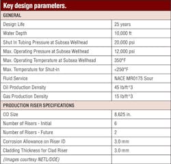
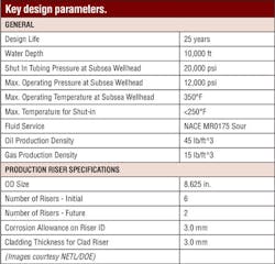
Additional participants in the project included BP, Shell, Petrobras, ConocoPhillips, ExxonMobil, and Chevron. The project was tasked with performing dynamic analyses and other second-level evaluation of riser concepts that had passed an initial concept evaluation and had included key design parameters.
Host vessels for the riser evaluations were semisubmersibles and disconnectable-turret-moored and captive-turret-moored FPSOs.
Semisubmersible
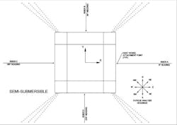
A semisubmersible hull arrangement with conventional four columns and four pontoons was selected for this study. Catenary-type risers are typically hung-off a semisubmersible from a receptacle structurally affixed to the pontoon. The riser hang-off location can be either on the inside of the pontoon or along the outside of the pontoon.
Motion of the riser hang-off location was a concern. The farther that the riser attachment point is from the center of the vessel, the larger the roll/pitch-induced heave that the riser will experience. Thus, it is advantageous to hang off the riser from the inside of the pontoon. However, if a riser concept is shown to meet design criteria when hung off from the outside of the pontoon, there is a high likelihood that it is a viable design when hung off from the inside of the pontoon. Therefore, for this study it was assumed the riser was hung-off from a point along the outside of the pontoon. The lateral distance from the center of the hull to the riser hang-off location was set to an even 100 ft.
For analysis purposes, the riser was modeled such that the riser heading was perpendicular to the pontoon. Three environment directions were analyzed for the design storm conditions used to assess riser maximum load capacity: in-plane taut, in-plane slack, and out-of-plane.
For assessing fatigue performance of riser concepts, three additional riser models were created that were identical to the one model used for strength assessment except for their vessel attachment point and heading. One riser model at a single heading was thought to be inadequate to obtain the most damaging condition, because the fatigue sea state probabilities of occurrence vary with direction of the environment. To increase the odds of capturing the minimum fatigue life, all four riser models were analyzed to the same fatigue sea states.
FPSO
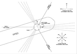
The FPSO considered for this study was turret-moored, with a turret that was located internal to the ship-shaped hull. The risers were hung-off from within the turret and the hull was free to weathervane about the turret. Therefore, the ship-shaped hull’s orientation relative to the risers, which were fixed relative to ground and the turret, was dictated by the relative directions of the environment’s constituents (i.e., waves, wind, and current). The extra degree of freedom and complexity that a freely weather vaning host adds led to the decision to analyze three riser models, where each riser model differed only in its hang-off location and heading. The three riser models, which were arranged 120 degrees from each other, were used for both riser strength assessment and fatigue assessment. The risers were arranged in the sectors between the mooring line groups.
For evaluating riser maximum load capacity, three environment directions were analyzed similar to the semisubmersible vessel case. With three environments and three riser models, seven unique and two duplicate riser/environment heading combinations at 30 degree intervals were achieved. This provided a solid possibility of obtaining the worst condition for the riser, considering both surge/sway offset and pitch/roll motion affecting bending at the top of riser. The eight fatigue sea state headings analyzed with the three riser models (where, as mentioned above, one riser is modeled in each of the three sectors created by the mooring pattern) should provide adequate coverage to estimate the minimum fatigue life of a riser concept.
Installation assessment
The riser configurations that show promise as viable alternatives for high-motion vessels are listed below.
- Distributed Buoyancy
- Lazy Wave Riser (LWR)
- Steep Wave Riser (SWR)
- Discrete Buoy
- Hybrid Riser Tower (HRT)
- Tension Leg Riser (TLR)
Of these four configurations, the lazy wave riser and the hybrid riser tower are technically mature, with installation histories. The tension leg riser concept was thoroughly studied by Mobil in the late 1990s with creation of established steps to install the submerged buoy. The other components of the tension leg riser (which are the catenary risers hung-off the buoy and the catenary jumpers) are common items.
The steep wave configuration is the least mature of the group, but it has common elements to both the lazy wave riser (buoyancy modules) and the hybrid tower riser (riser base). The advantage that a lazy wave configuration has over the steep wave is that the section of riser downstream of the buoyancy modules (downstream from the sense of pipelay direction) provides weight to sink the buoyed region. But since the steep wave riser’s buoyancy modules are arranged very near the bottom of the riser another means of overcoming their uplift force is required. The obvious two options to accomplish this are:
- Make the riser base overly heavy
- Add rigging that pulls the riser base down.
The second option has been previously performed when installing a hybrid riser tower system. Although the first option seems simple, it would add hundreds of tons of weight to lift and maneuver offshore.
Technology gaps
The following technology gaps were identified for the design scenario presented here:
- Swivel capable of withstanding internal pressure approaching 20,000 psi.
- Thermal insulation capable of service at 350°F.
- Riser base flow path components capable of containing 20,000 psi internal pressure.
- Use of composite-reinforced pipe as a flowline/production riser.
- Use of a captive-turret FPSO in the GoM.
- Proven inhibitor methodology for 20,000 psi/350°F.
Conclusions
A conventional semisubmersible and a captive-turret FPSO have riser payload capacities that allow them to support heavy riser systems. A carbon steel riser sized for 20,000 psi SITP was the base-case as a lazy wave riser for these two high-motion vessels. A simple SCR modeled with the same carbon steel wall thickness is not expected to meet fatigue criteria. The fatigue benefit of using titanium pipe locally in the touchdown region in an otherwise steel-constructed SCR should also be investigated.
For a disconnectable turret FPSO, the discrete buoy concepts, TLR and HRT, are the most promising from the standpoint of riser payload. This is because the host vessel supports only the jumpers spanning from the turret to the submerged buoy. For these systems, carbon steel jumpers with titanium stress joints and titanium jumpers with titanium stress joints are feasible from a strength perspective. Within NETL, research is ongoing to develop higher strength composite metals that would further improve riser performance in extreme, deepwater environments.


