Radioisotope technology helps ensure pipeline flow
Matt Wilson
Tracerco
The growing demand for fossil fuels means an increasing number of subsea pipelines to transport the oil and gas. This, in turn, has led to the application of various radioisotope technologies to help offshore operators achieve effective pipeline flow assurance.
These well-established and radiologically safe techniques are similar to the way in which the medical profession uses X-rays and radioisotopes to diagnose clinical conditions. For example, a pipeline assessment is similar to an X-ray of a patient in that it allows analysis of the object’s contents non-intrusively, whether those contents are hydrocarbons or human bones. In the medical world, a patient can ingest low energy barium so an internal assessment can be made on the condition of his digestive tract. Similar assessments can be made of pipeline and process systems by introducing an appropriate isotope.
The technology offers several types of inspection services for pipelines that are in operation. The data determines whether local deposits have caused blockages, and whether they are present in limited locations or distributed through the line. The total volume of deposits and percentage bore restriction within the pipeline also can be identified. Measurements can tell whether the annulus of a pipe-in-pipe system is dry or flooded with seawater or product. In combination with pig tracking, radioisotopes are indispensable for pipe assessment or for leak detection.
The technology also has been developed to establish pipeline conditions over time with a non-intrusive wall thinning assessment. These techniques can increase productivity, lower operational costs, and allow the optimization of downtime.
Longer tiebacks
As remaining reserves of oil and gas become more difficult to access and fields previously not economical become viable, there is an increasing requirement for longer subsea tiebacks to production facilities. The flowlines in longer tiebacks are more prone to blockage from deposits such as hydrates or waxes. As assets mature and as pipelines require more routine inspection, non-intrusive measurements are an essential tool to reduce downtime.
Over the life of an asset, it is important that the challenges of aging are addressed with effective and reliable techniques. If deposits/blockages and corrosion points form, they can be examined and quantified so the appropriate intervention can be taken before a small problem becomes much larger, potentially resulting in pipeline failure and unwanted emissions to the environment.
Using techniques applied in oil and gas processing for more than 50 years, many different pipeline scenarios can be determined from outside of the pipeline. The problem arises when the pipeline is buried, as in many subsea applications, and access is difficult. In such case, tracer techniques, similar to the barium used in medical technology, can determine deposit location (and flow regimes).
Following are some recent examples of the radioisotope technology; discussions of the scope and limitations of the technology; and indications of the benefits the technology brings to oil and gas operators.
Radioisotope applications
Radiation is all around us all the time, whether from natural sources or from manmade devices encountered in everyday life – and contrary to public perceptions of radiation, poses no tangible risk. Examples are:
- Naturally occurring radiation in materials such as granite
- Cosmic radiation which we receive every time we fly on an airplane
- Airport scanners for luggage checks
- X-Rays for broken bones
- Treatments for illnesses such as cancer.
If we use radiation in an pipeline application, an isotope with penetrative power is required to pass through steel pipes or process vessels. Particles of radiation come in three forms:
- Alpha particle, which will not pass through paper
- Beta particle, which will pass through paper but not steel
- Gamma ray particle, which will penetrate steel.
Gamma radiation has been used in diagnostic techniques in the oil and gas industry for more than 50 years.
Flow assurance
Flow assurance can be defined as the steps required to ensure satisfactory flow from the reservoir to the point of sale, and the desire to understand, map and study the volatile and unpredictable oil and gas flow from reservoir. This is a challenge. The uses of medical-based radioisotope techniques in oil and gas flow assurance include the following:
- Identify, locate, and quantify materials such as waxes, scales, sand, sludge, and hydrates that block pipelines
- Assess total pipeline deposits as part of a cleaning program to increase production
- Accurately assess and quantify pipeline condition as per corrosion condition models
- Accurately assess and quantify pipeline condition prior to pigging campaign
- Identify and locate pipeline restrictions such as stuck pigs
- Profile pipeline wax buildup over long time periods
- Assess and quantify flow measurements.
Liquid and gaseous tracing techniques are used regularly for all of the above in multiphase systems. The tracer is designed to follow a particular material through a system. Sensitive detectors are placed strategically on the outside surface of a pipe (or other process system) where they detect the selected tracer as its flows past. These can directly measure fluid velocity, flow rate, phase distribution, and deposit inventory.
By measuring the time between detector responses and knowing the distance between the detectors, the mean linear velocity can be calculated. If full bore turbulent flow can be assumed, then the velocity can be converted to volumetric flow based on the pipe internal diameter. Accuracy depends on the precise circumstances, but the mean velocity usually can be measured to better than +/- 0.5%.
The accuracy of the volumetric flow is influenced by the known internal cross sectional area of the pipeline.
The basic principle of a tracer investigation is to label a substance or phase and then follow it through the system using suitable detectors. Look at tracer studies from a problem-solving point of view. If problems of fluid transport can be described in terms of “when?”, “where to?”, and “how much?” then they can be solved with tracer techniques.
The basic requirements of a tracer are as follows:
- It should behave in the same way as the material under investigation
- It should be easily detectable at low concentrations
- Detection should be unambiguous
- Injection and detection should be done without disturbing the studied system
- The residual tracer concentration in the product should be minimal.
Frequently, more than one radioisotope will work and the factors that are important in the selection of the tracer are the:
- Half life
- Specific activity
- Type of radiation
- Energy of radiation
- Physical and chemical form.
While tracer studies usually are employed in basic flow measurement, they have also been used successfully in flow assurance to measure the location and extent of solids within a pipeline. In this application, the flow rate through the system must be known and must be kept constant. Detectors are positioned at known distances along the pipeline.
A pulse of tracer is added to the pipeline and its velocity past detector positions is measured. Using the velocity and flow rate, the average bore size can be calculated between detector locations. This measurement can give critical information prior to any proposed pigging operations and provides operators with the confidence to successfully run pigging campaigns, knowing a pig will not get stuck and cause significant production losses.
This technique is used when the total deposit inventory of long lengths of line needs to be known. Access is not needed to the entire pipeline (it can be buried or subsea), just specific positions for detector location. For example, a recent study of a 110-km (68-mi) pipeline between two offshore platforms was conducted with single measurement positions at each end of the line to give a total deposit inventory of the line. A similar study was conducted with subsea detectors deployed every 10 km (6.2 mi) along a 60-km (37-mi) pipeline to provide information of the total amount of deposit in each 10-km section.
The application of the flow assurance technique can be summarized in the flowing steps:
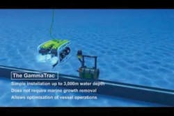
- Deploy GammaTrac detection units subsea at known intervals. The units have wireless communication, allowing a permanent deployment subsea to allow for multiple studies. This is especially useful when determining wax build up rates.
- The units are deployed at strategic locations. This is critical when the pipeline is laid on a seabed that has many undulations or depth changes.
- A suitable radioisotope is injected and its passage is recorded for analysis. On evaluation of the results, the units can be redeployed at different locations to provide further more accurate data over shorter distances.
- The data is gathered and evaluated by a qualified engineer at the worksite for instant feedback to the client.
Wax build up
The tracer study can determine wax build up rates within oil lines such that a pipeline cleaning pigging strategy can be implemented and production increased. By determining an accurate build up rate, both time and money can be saved with any pipeline intervention and cleaning operation. The position and build up of waxes can increase the risk of getting an object (such as a cleaning pig) stuck. The cost of removal and/or recovery of a stuck pig can be significant and is likely to involve many specialist third-party contractors. The lost production time can be expensive, so prevention is preferable to cure.
Pipeline deposits
The deposit profile within the whole pipeline can be determined by enhancing the above study with the deployment of data gathering units. The case study was for a 70-km (43.5-mi) pipeline with units placed subsea at 15-km (9.3-mi) intervals. A suitable and optimized radioisotope was injected into the pipeline, and led to the discoverey that 6% of the 18% total pipeline deposit volume was contained within a 15-km section.
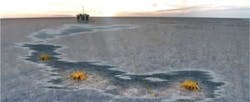
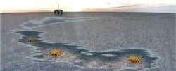
(Left) Radioisotope is injected and its passage recorded for analysis. (Right) Data is gathered and evaluated at the worksite, providing instant feedback.
Due to the requirement to pig the line as part of a cleaning program, further investigations were required. The non-intrusive gamma ray transmission technique was deployed. The results showed there were local deposits resulting in only a free volume of 5%. Therefore, a pig would have stuck in the pipeline. Appropriate action was then taken by the client.
Flow profiling
Offshore processing is complex and, with ever evolving fields and deeper wells producing more and more three-phase flows, it is imperative that slugging is understood, monitored, and controlled. With an array of in-field flowlines tied back to an FPSO, the need to understand and map slugging is also key for pipeline integrity. With real-time data collection and analysis, a series of in-field flow lines can be accurately measured and monitored. The size and shape of slugs of material can be sent directly to the operations team to alert them to the potential for a process upset. Likewise, long-term slugging effects be detrimental to the pipeline, and hence the data can be used to confirm modeling information.
Hydrate formation
Hydrates form within pipeline systems and have a detrimental effect on process operating conditions, resulting in lost production through blockage and restriction. The need to understand where and what size a hydrate plug or restriction is present in the pipeline can assist in getting the pipeline back into full production.
In one case, the operator’s gas well started to produce water much earlier than predicted. As such, a standard procedure of injecting methanol was started but production stopped and a hydrate plug was suspected. The operator added a chemical to the line to clear the restriction but a pressure build up indicated the chemical injection had little effect.
The real-time, non-intrusive scan of the line showed the pipeline density profile and therefore the hydrate, methanol, chemical, and gas all could be located and monitored during remedial operations.
Conclusion
Radioisotope technology offers powerful and proven techniques to accurately measure the amount and location of pipeline contents such as waxes or hydrate deposits when the pipeline conditions are uncertain. Until recently, these direct, non-intrusive measurements of pipeline contents were thought to be impossible, but many operators have used the technology recently, and its use is rapidly increasing worldwide.
The benefits of using tracer and scanning techniques to detect deposits within pipelines are summarized as follows:
- The techniques “make process systems transparent.” Rather than guessing at what might be wrong, the techniques allow users to make accurate, informed decisions with respect to further intervention or mitigation.
- All techniques provide online and real-time results, allowing optimization and troubleshooting to be performed in-situ.
- Small teams of engineers can do the scanning and tracer techniques described above
- Most pipeline systems/subsea production systems are complex. But the techniques allow the complexity of the system to be divided into individual components and assessment made of the performance of the individual parts.
Acknowledgment
Based on a paper presented at the Offshore Middle East Conference held Oct. 12-14, 2010, in Doha, Qatar.
Offshore Articles Archives
View Oil and Gas Articles on PennEnergy.com


