Deep compressional wave imaging improves understanding of Gulf of Mexico play

Method helps delineate structural parameters, identify reserves near salt dome
Doug Patterson, Gennady Koscheev
Baker Hughes
Structural features such as salt domes have frustrated operators in theGulf of Mexico for decades. The crystalline (evaporite) nature of the salt causes it to “flow” easily, while the unconsolidated, lower-velocity sediments surrounding it are much “slower.” The resulting velocity contrasts hinders understanding of structural traps and causes ambiguity about where to position wells in relation to the salt structure.
Surface seismic can span miles of formation. However, its poor vertical resolution and the combination of complex shapes of steeply dipping flanks, adjacent overburden strata, and strong acoustic impedance and velocity contrasts at the sediment-sale interface prevent surface seismic from being able to detect bedding changes in close proximity to the salt structure. Conventional borehole imaging, on the other hand, has excellent vertical resolution but its depth of investigation is limited to fractions of an inch near the borehole wall.
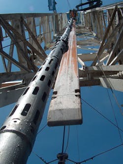
Baker Hughes has developed an acoustic acquisition, processing, and 3D visualization method that uses compressional body waves generated by an acoustic dipole source to better understand a fairly mature Gulf of Mexico play. This method, called deep compressional wave imaging (DCWI), enabled the operator to identify and determine the position of three fairly large faults, improve understanding of the structure above the salt dome, and define a future reservoir target. Integrating the acoustic data with induction logging data also identified an additional 30 ft (9.1 m) of pay in another target area.
Finding hidden targets
Interpreting seismic data in close proximity to structural features such as salt domes that have resulted from the movement of salt, or halokinesis, is well known and well documented throughout the history ofdrilling in the Gulf of Mexico. Halokinesis produces bedding disruption and complexity in the sediments surrounding the salt structures.
Because of the poor vertical resolution of surface seismic data, smaller targets that may hold economically viable reserves may not be easily imaged from the seismic data, and structural complexities such as faults and targets underlying the salt bodies may be missed entirely. Similarly, conventional borehole imaging services can only detect features at the intersection of the tool with the borehole, so outlying faults and fractures cannot be identified and critical formation details can be missed.
Deep reflection shear wave imaging (DSWI) overcomes this limitation by mapping acoustic reflections away from the borehole, even if they are not intersecting the wellbore. The DSWI service provides an image of the reflective feature, its distance away from the borehole, the magnitude of the reflection, and its strike orientation. The identified features can then be integrated into the reservoir model to aid in field development.
While typical DSWI methods can be employed, the DSWI range of investigation is limited because of the extreme low shear velocities of the sediments surrounding salt domes in the Gulf of Mexico.
An enabling innovation
Conventional DSWI tools have two types of sources: monopole and dipole. Initial borehole acoustic imaging relied on using the monopole source and focusing the analysis on the radiated compressional body waves that were reflected back to the borehole. This type of imaging could be used to determine imaged structures’ dip, but it did not provide any azimuthal information. More recent efforts with the monopole source have focused on using azimuthal receivers for directional sensitivity, but the tool size limits its use to high frequencies. These high frequencies and the accompanying formation attenuation severely limit the range of investigation.
DCWI is an innovative approach that uses the algorithm for DSWI and concentrates on the low frequency compressional body waves generated from a dipole source to offer an effective and efficient solution in unconsolidated formations surrounding salt domes. Using techniques similar to those used in seismic processing, reflections from formation features up to 100 ft (30.5 m) away from the borehole can be extracted from the cross-dipole shear waveform data.
The compressional body wave, generating from the dipole source, is also at a lower frequency than the monopole source, offering the ability to see deeper and with reduced attenuation effects since the wave’s attenuation is a function of the frequency raised to an exponential. The dipole’s directional radiation pattern, coupled with the four cross-component dipole information, enables optimization of the azimuthal sensitivity orientation. Although there is still the well-known conundrum of the 180° ambiguity associated with the dipole. This issue can be resolved through application of other information such as geologic knowledge, wellbore trajectory, or other information to determine the direction of returned reflected waves. Further enhancement is achieved by increasing the recording length by 70%, facilitating imaging deep into the formation, at depths of investigation of up to 100 ft or more, given the right conditions.
Gulf of Mexico case study
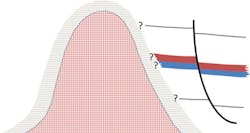
In an exploration project in the Gulf of Mexico, there was a large umbrella of uncertainty on the surface seismic as a result of a salt dome surrounded by unconsolidated sediments.
A large fault was observed in the seismic data in the upper section, to the west of the study well. However, the fault was not discernible from seismic to the east, even after reprocessing of the seismic data.
Using DCWI and processing the acoustic data for the compressional image, the fault could be seen to the east, striking northwest-southeast with a dip of approximately 45°. After the acoustic data had been merged with the seismic data, it became possible to identify the position of the fault on the seismic section, aiding the understanding of the structure above the salt dome. This understanding will help in defining a future reservoir target. Once defined on the seismic, the throw of the fault was estimated to be around 50 ft (15 m), which corresponds to that seen on the compressional acoustic deep image.
Further processing for the amplitude of the acoustic data also enabled better bed definition, helping to improve the detail of the seismic in these unconsolidated formations, especially since the seismic around the salt dome is unclear and uncertain at depths and offsets around and above the dome. Additionally, the acoustic data were integrated with, and validated by, other log information.
A 3D induction instrument was run to evaluate the possibility of laminated pay above the main section of interest in the well. Three sands were detected. The uppermost was easily identified as gas-bearing from conventional log measurements, but the lower two sands were not easily detectable, and appeared as shales and with low resistivity. The results indicated, in spite of a significantly enlarged borehole, an additional 30 ft (9.1 m) of pay in these two lower sands. Although not the main exploration target, these sands are intended to be exploited in other parts of the field.
In addition to the laminated pay, and again in spite of large washouts, the 3D induction was processed in high-salinity mud to determine structural dips, confirming the structural dips to be in general less than 10°. This corresponded to the observations from the seismic and field expectations. However, the dip processing also indicated several intervals of complex growth faults and associated discontinuities, and these corresponded with the reflectors seen on the DCWI.
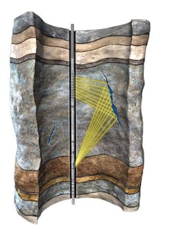
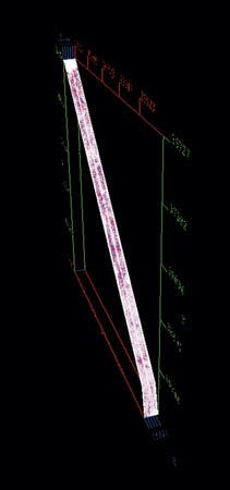
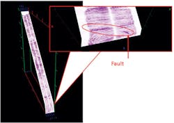
With the 3D induction results, the fault could only be seen near the wellbore. With the processed compressional wave image, it was possible to determine the dip and strike of the reflector as far as 89 ft (27 m) away from the borehole. Some of the complexity around the fault could also be seen.
Overall, the DCWI method identified three fairly large faults, with one subseismic fault and several other small faults of discontinuities. The gas- or light hydrocarbon-bearing sand above the low-resistivity pay was visible on the DCWI because the compressional wave is sensitive to hydrocarbons.
3D visualization
After processing was complete and the appropriate viewing planes determined to optimize the visualization of the reflectors, the entire logged image was presented in a 3D volume for comparison to surface seismic data.
This image could be rotated to display different views, as required for viewing on the seismic array cross-section(s).
As the case study illustrates, the DCWI method of employing compressional body waves generated from the dipole source can enhance understanding of the complex structure around a salt diaper and in unconsolidated sediments exist throughout the Gulf of Mexico. In the well described in this article, the method enabled the recognition of key structural details to refine the position of targets in the subsurface. The inherent higher frequency of this borehole acoustic data, which is more than two orders of magnitude higher frequency as compared to surface seismic, yielded finer detail to detect structures below surface seismic capabilities. Additionally, the crucial positioning of the transmitter and receiver along the borehole made it possible to recognize structures that would not have been recognizable or trackable away from the borehole with any other acoustic imaging technology.
A better understanding and insight into the structure at depth was attained, not only at the borehole, but also away from it. Depths of investigation were greater than those achievable with DSWI in these slow unconsolidated formations. In today’s drilling and business climate, obtaining more information from penetrated wellbores is an advantage in maximizing the available information efficiently, especially in a 3D context.
Future development
Future development of the DCWI service is being extended to a 3D volume, enabling visualization of the salt dome and associated structures. In horizontal wells, this 3D visualization enables detection of layers above and below the wellbore as well as reflectors often associated with natural fractures and faults, both intersecting and non-intersecting with the borehole.
Future integration of this technology with vertical seismic profiles and borehole image logs is expected to further improve the level of detail regarding the structure complexity at the wellbore and penetrating into the formation. Consequently, greater refinement of the seismic picture will be possible, making exploration and development objectives easier and more efficient to achieve.