DRILLING TECHNOLOGY: PDC technology focused on efficiently drilling extra-hard formations
In 1999, Shell UK Exploration and Production (Shell Expro) decided to drill an additional well in the Kingfisher field (UK sector of the North Sea) in order to optimize the production profile from the over-pressured Heather Sands reservoir. This second well, 16/8a-HP2, would be drilled from a nearby vacant slot, which had already been pre-drilled to the 20-in. casing shoe at 3,407 ft.
During the planning stages of 16/8a-HP2, great focus was placed on improving drilling efficiency relative to HP1. Offset performance data from the initial three Kingfisher development wells (BP1.1, BP1.2, BP2.1) was useful down to 13,000 ft true vertical depth (TVD) but HP1 was unique in the field, with a targeted true vertical depth projected to reach 15,000 ft.
From previous experience, it was determined that optimizing drilling efficiency in the 12-1/4 in. hole section was critical to project economics. Formations that proved particularly problematic in the 12-1/4 in. hole section of well HP1 included the abrasive Kimmeridge Clay and the hard and abrasive Brae Formation. The detailed planning of well HP2 was further exacerbated by the lack of wireline log data from well HP1, which seriously limited the ability to complete any rock strength analysis that may have helped to improve bit and cutter selection.
Steerable motors
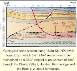
To achieve directional objectives in the 12-1/4 in. hole section, the operator needed to utilize steerable motor assemblies to hold angle at 22 degrees through the Kimmeridge, Brae 1, and upper Brae 2 units. A build and turn in the lower Brae 2 and upper Brae 3 units provided a final inclination of 43 degrees at the 9 5/8 in. casing point.
The HP1 well was the closest offset well and the only well in the vicinity that drilled a 12 1/4 in. hole through the hard and abrasive Kimmeridge and Brae. Two heavy set polycrystalline diamond compact (PDC) bits sustained heavy wear after drilling only 218 ft, raising questions as to whether the formations were actually economic to drill utilizing PDC technology. The remainder of the 12-1/4 in. section on HP1 was completed using tungsten carbide insert bits, but at a low rate of penetration (ROP).
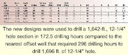
During the planning of the HP2 well, it became apparent that the very latest materials, design and application techniques would need to be utilized to make a marked improvement to the well economics. The Hughes Christensen application team (hereafter bit company) was in the advanced stages of field-testing new PDC designs that included improvements in cutter technology, stability, and hydraulics. The combination of these two events led to cooperation between the operator's well engineers and the bit company's application and design engineers that produced two new PDC designs. This led to greatly improved performance, when compared to both offset wells and same well bit runs.
Well planning
The 12 1/4 in. section was to be maintained on a 22.3 degree tangent at an azimuth of 156 degrees through the Chalk, Valhall, Humber, Kimmeridge and the Brae 1, 2, and 3 formations. The objective of the 12-1/4 in. section was to isolate the troublesome Brae sequence and provide the formation strength required to drill the higher pressured (11,750 psi) Heather Sands reservoir.
Bit/BHA (bottom hole assembly) selection was critical to well economics in this section. After careful consideration, engineers decided the best approach would be to use low speed high torque mud motors to achieve the best possible penetration rate through the interval. Since high shocks/vibration had developed in various offset wells, the use of mud motors was considered essential to provide de-coupling with the rest of the BHA. A 5:6 lobe motor was the clear choice and the drill bit companies were tasked to come up with PDC designs that would give the maximum durability as well as meet the directional requirements.
New 12-1/4
Two designs were developed for this application. Very early in the discussions between the team members it was established that two very distinct applications existed. The Kimmeridge-Brae 1 section presented the greatest challenge, as the offset performance tended to show this was economically incompatible with current PDC designs. Stability and abrasion resistance were perceived as key. In addition to continued stability and abrasion resistance, the requirement of steerability was added to complete the build from 22 degrees to 43 degrees in the Brae 2-Brae 3 section.
To aid in bit development, the team studied dull bit pictures available from previous Kingfisher wells. They also analyzed data from other well operations in the Central North Sea that contained hard abrasive formations. From this extensive analysis, engineers determined that technology development already underway would be well suited to improve performance on the upcoming Kingfisher well.
Various advanced proprietary drill bit dynamics models were extensively used to predict stability, wear rates, dynamic loading, and hydraulic efficiency. These modeling techniques were invaluable in designing bits of the correct profile, cutter type, and cutter size, such as the HC609 design which has nine blades set with 19 mm cutters. The cutter types used were chosen according to the position on the bit. Maximum gauge protection was utilized to ensure the bit stayed in full gauge. Nine nozzles were fitted and hydraulics were further enhanced using computational fluid dynamics. Also, the HC408, an eight bladed 13 mm cutter design, was also developed to address the steerability issues of application two. This bit was to have engineered cutter placement to combine aggressiveness with durability.
PDC bit development
These new PDC bits combine the very latest in advanced technology and a revolutionary design process to achieve maximum performance and consistency in defined applications. The tools available to the bit development team were split into three areas of advanced technology:
- Advanced stability concentrating on, but not limited to, the resistance and reduction of lateral vibration commonly called bit whirl.
- Innovative cutter technology related to diamond properties and thickness plus external geometry.
- Computational fluid dynamics (CFD) modeling of every new bit with regard to hydraulic cleaning efficiency.
Once a cutter breaks or spalls, it wears very quickly. In some applications, operators continue to use the PDC bits even after breakage occurs to get the maximum life from the bit. They are hesitant to pull the bit until they know it is totally worn out. In this situation, the dull can indicate smooth wear, but in reality, the major dull characteristic was impact damage from vibration instability. From their studies, engineers defined two types of stability:
- Primary stability is the tendency of a bit to drill smoothly or how fast the bit locks-in and becomes stable. In field operations, this influences the amount of time the bit is operating in a stable drilling mode. This stability is obtained through cutter layout using both high and low imbalance design strategies depending on the application.
- Secondary stability is how severely the bit vibrates when it is unstable, which is related to its ability to resist drilling system instability. In field operations, this influences the severity of dynamic cutter loads when the bit drills in an unstable mode. We recognized that by taking certain steps, vibration severity could be significantly reduced while in the unstable state. This improves durability by protecting the cutters from impact damage and the reduced vibration is advantageous to the entire BHA.
Two new proprietary technologies for controlling secondary stability are:
- The Lateral Movement Mitigator (LMM) provides a bearing that limits lateral motion when bits whirl. Although LMM limits radial deviation, it does not hinder the ROP.
- Brute (backup cutters that are radially unaggressive and tangentially efficient) inserts are a new external feature. These cutters use a thick diamond table imbedded in a wear knot and are oriented so they cut tangentially, but not radially (sideways). The polished diamond provides a low friction surface orientated to shear rock if the leading cutter is damaged.
Cutter technology
The three different factors to consider when discussing cutter technology are:
- External cutter geometry and placement strongly influences impact resistance and generally varies 0-30 degrees. For example, when impact occurs, energy is directed into the carbide substrate, instead of along the diamond table, decreasing the likelihood of spalling and catastrophic failure.
- Internal cutter geometry and interface design varies to obtain a balance between durability and efficiency, and the interfaces are engineered to provide optimum performance with the table thickness used.
- Cutter size and profile from previous studies determined that more diamond volume will lead to increased durability for a given design. However, with the advent of new PDC cutter technology care must be taken to ensure that selection of very thick diamond cutters does not result in an inefficient cutting action due to high WOB (weight on bit) requirement.
Recent advances in the application of CFD to optimize the hydraulics of PDC drill bits have allowed engineers to use the process in conjunction with the new designs. Initially, the process of meshing the model and optimizing the hydraulics of a bit using CFD would require up to one month to complete.
Now with faster computers, new meshing techniques automated data analysis and new findings in the applications of CFD to PDC drill bits, the time required to complete the CFD process has been reduced. Although with the many new enhancements applied to the new bit line it is difficult to isolate those benefits due solely to the CFD analysis, the new hydraulics optimization method most certainly contributes to better cleaning, cooling and reduced erosion. Case studies show the new bits drill faster and farther.
Performance
The base plan was to drill the section with another nine bladed PDC bit consisting of different sized cutters. However, after drilling only 50 ft in the mid/base Kimmeridge, the bit came out very heavily worn and 3/4 in. under gauge, indicating the Kimmeridge was more abrasive than had been assumed.
After seeing the condition of this PDC design, it was certainly felt this was the right time to try the new designs. The 12 1/4 in. HC609 was picked up and drilled the remaining Kimmeridge and Brae 1 sequence which was considered the most challenging interval. At 13,850 ft, it was decided to pull out of the hole due to an increasing drop tendency from 0.4 to 1.5 degrees/100 ft, which was deemed unacceptable as correction runs and would have proved slow and problematic. On the surface, it was found that the near bit stabilizer was 7/32 in. under gauge and the cause of the drop tendency. The bit was still in good condition and was graded 4-7-WT-S-X-I-HC-BHA.
Due to the increased confidence in the new designs, the second custom design bit (HC408) was placed on a steerable motor assembly to initiate the build and turn required before the casing point. This bit drilled a total of 507 ft of Brae 2 to 14,437 ft at an average ROP of 12.1 ft/hr. The bit was finally pulled for low ROP and graded 4-8-RO-S-X-3/16"-BT-PR. The sleeve stabilizer was also 3/8 in. under gauge.
Due to the lack of availability, no more suitable new bit designs were run. The performance of these standard bits was far below the step changed offered by the two application specific PDC bits.
Cost/ft calculation
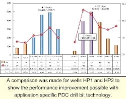
Bit performance is ultimately evaluated in cost/ft, for all bits used in the interval discussed. The cost/ft is also shown for HP1 to show the performance improvement possible with application specific PDC drill bit technology.
null
Operating cost/hr = $4,200
Drilling cost = operating cost x drilling hours
Trip cost = Trip time (1hr/1000 ft) x operating cost
Since all bits run through this section were on similar BHA's and at similar drilling parameters, RPM (117-137), flow rate (770 gpm) and standpipe pressure (3,100-3,340 psi), it was considered a good benchmark to evaluate the new technology bits.
Enhanced PDC bit stability, cutter technology, and optimal hydraulic efficiency can give a step change in performance when applied correctly. The use of advanced wear and dynamic models, tailored to a specific application reduces costly iterations and offers a more effective solution to PDC bit design.
Drilling system optimization services will extend tool life and improve overall performance in tough applications. The use of real-time downhole vibration measurement allows optimization of drilling parameters to improve performance.
Acknowledgement
Shell's Mobile Drilling Unit and Hughes Christensen closely cooperated in this program, as did the Santa Fe 140 team. Mark Dykstra, Matt Isbell, Mike Doster, and Matt Meiners provided research and technical input; Aaron Ochsner, Will Heuser, and Jack Oldham provided designs; Will Heuser and crew provided CFD support; Mike Williams, Peter Hoyes, Sandy Dunn participated in the cross-functional team.


