P&A innovations increase efficiency, safety

In the field, a combination of advanced technology and aggressive engineering often provide the best solution
Philip O’Connor
Weatherford International Ltd.
Plug and abandonment operations face a long list of challenges, including rising costs, safety concerns, environmental issues, and rapidly growing demand. Conventional methods and tools are frequently unable to address these concerns. Instead, the solutions are being found in new technologies that are yielding improved levels of efficiency and performance.
These advances contrast with traditional approaches, such as jackup rig installations, that are typically slow-to-mobilize and expensive. Traditional rigless P&A equipment comes with cost and safety concerns, and snubbing units generally expose personnel to safety risks and can be difficult to move from well to well.

Many of the recent advances center around the development of versatile and compact rigless intervention and well abandonment systems. These systems are fit for purpose and can include hydraulic pulling and jacking units, cantilever systems with light duty work decks, and casing jack configurations. Lightweight and modular and with a minimal footprint, these systems provide new levels of mobilization and flexibility.
They are at the core of a suite of technologies that provide a scalable P&A solution ranging from casing jacks to light-duty work deck and cantilever systems, to full-function pulling and jacking units. Further integration with a larger scope of service draws on multiple resources including wellhead diagnostics, running bridge plugs, tubing cutting and removal, and remedial cementing to improve safety and efficiency.
These technologies and capabilities combined provide the tools for innovative, engineered solutions that improve performance on a range of P&A applications.
Growing demand
Complicating the P&A picture is the greatly increased demand projected for services due to 2010 changes in decommissioning guidance for wells and platforms in the Gulf of Mexico. The new guidelines from the Bureau of Ocean Energy, Management, Regulation, and Enforcement are expected to add to activity by making P&A actions dependent on well and structure status instead of the lease status.
This anticipated increase comes on the heels of record increases in temporary and permanent abandonments in 2008 and 2009, due in part to hurricane damage. According to a recent webinar conducted byOffshore,1 2009 capital expenditures were $650 million to $1.4 billion, accounting for 835 permanent abandonments, 744 temporary abandonments, and 214 structure removals. The activity is about 50% ahead of a busy 2008.
The new decommissioning guidance affects an inventory of approximately 3,500 shallow and deepwater wells that have been idle for five or more years. Those wells must be plugged and abandoned in the next three years. In addition, there are approximately 2,000 wells idle for less than five years and an additional 3,500 wells that have been temporarily abandoned. All told, there is a very large waiting list of P&A operations that must be addressed over a relatively short time period.
New approach
Addressing this well inventory will require a marked change in the efficiency and innovation of P&A operations. A key part of this change is the combination of advanced technology and aggressive engineering that is already providing solutions for many P&A challenges.
The three following cases, one onshore and two in the Gulf of Mexico (GoM), illustrate the increasing importance of innovative thinking and equipment to P&A performance. This enhanced performance is central to improving safety and reducing costs.
Each case depended on continuous communications and extensive collaboration with the clients. All three presented unique circumstances that required innovation and the development of fit-for-purpose components and equipment.
Leaning six-pile platform
A 15° lean made P&A work on a hurricane-damaged, six-pile platform particularly challenging. The structure was loaded with production equipment and prior to the storm had been operational with 10 producing wells and one partially drilled conductor.
Underwater inspections showed one corner leg of the platform had penetrated the supporting shale on the seafloor and cause the structure to lean. Nevertheless, the structure was found to be relatively stable and well conductor damage was limited to bending at or below the mud line.
To conduct P&A operations on the live wells, the platform was secured with a second, four-pile platform positioned at the leaning corner of the structure. Extensive laser surveying established the exact relations of the wellheads to the new structure.
Several P&A options were considered and rejected for safety and cost reasons. A snubbing unit would have required a major engineering effort and would have put the wellheads in harm’s way. A jackup rig of sufficient size to cantilever over the well bay area would have been cost prohibitive.
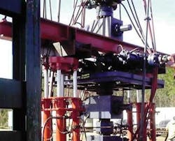
A new, lower load rating was established for the compromised structure. These specifications guided the development of a lightweight pulling and jacking unit. A modular design for the unit was used to provide high mobility and a small footprint. An integrated self-clamp skidding system allowed the unit to be easily skidded from well to well.
Design of the unit depended on close teamwork with customer personnel and strict attention to platform constraints. Limited deck space required measurement of each equipment component. Exact equipment weights were determined to ensure that the total equipment load on the structure fell within the weight parameters after allowing for an over-pull of approximately 100,000 lb.
Special wedge deck
To accommodate the intervention and well abandonment system, which includes the pulling and jacking unit, a specially-designed wedge deck was built and attached to the original drill beams on the damaged structure. Placed over the wells, it provided a level work area for the unit to perform pulling and jacking operations.
Plugging and abandoning operations involved an experienced crew working around the clock. Extensive training was conducted to familiarize the crew with the specialized equipment and the risks associated with working on a structure that was leaning at a 15° angle.
In phase one of operations, a daylight crew was deployed to the platform to begin the wellhead diagnostics. Phase two involved wireline work and plugging of all open perforations.
During this time, the new hydraulic pulling and jacking unit was being manufactured and set up per the operational requirements and client requests. Tests were performed to simulate bends in the production tubing and casing while running bottomhole assemblies.
The intervention and well abandonment system was then deployed to the platform and the pulling and jacking unit was assembled on the new wedge deck.
Once the pulling and jacking unit was in place, phase three began. Wireline inspection indicated that several wells would require coiled-tubing work to plug open perforations and meet regulatory requirements. Crane support was limited by winds in excess of 35 mph, so the rigless pulling and jacking unit, which can operate at nearly twice those wind speeds, was used. Significant savings were realized by having the unit support the coiled-tubing operations. The change also freed the crane for other work.
Custom hydraulic clamps
Moving the unit from well to well on the structure was efficient with moving times that average an hour on most wells. The skidding process benefited from custom-manufactured, hydraulically actuated clamps that fit on virtually any combination of beam width and flange thickness.
On completion of the coiled tubing work, phase four began by perforating, cutting and pulling the production tubing and casing. Safe and efficient retrieval and laying down of tubulars was enhanced by the load capabilities and compact design of the pulling and jacking unit.
An integrated jacking floor was used to remove stuck casing hangers. When a hanger became stuck in the wellhead, it was a simple operation to spear into the tubular to be pulled, and then use the built-in jacking system to remove the stuck hangers.
Phase five involved cutting the remaining well casings approximately 15 ft below the mud line. The pipe pulling and jacking features were used to trip 3 1/2-in. OD drill pipe with cutting assemblies into the wells. The cuttings for all of the well conductors were completed without incident. Boring and sawing equipment were used to lay down the cemented well conductors in 40-ft lengths.
The pulling and jacking unit was a cost-effective, safe, and efficient means to complete the job. It eliminated drilling-rig costs and the development of an alternative method. The unit was manufactured quickly and all necessary work was completed two months ahead of schedule, which resulted in significant cost savings. During the 299 days/49,476 man-hours spent on location, there were 2,276 Job Safety and Environmental Impact Analyses conducted with no recordable injuries or operational and environmental incidents.
Frac damage
Failure of a wing valve during fracturing operations on a newly completed 16,000-ft well released pressure that bent the 10 3/4-in. casing at approximately 12° just below the wellhead. After removing the drive pipe and cement to expose the bent casing, it was decided to rig-down the wellheads and remove the damaged pipe.
Mobilizing a rig and crew presented significant time and cost constraints. To expedite work and safely cut expenses, the alternative solution specified a 385-ton casing jack, heavy-duty work beams and other specialized P&A equipment. Operations began with removing 5 1/2-in. and 7 5/8-in. casing hangers. Free travel of the hangers required jacking them out at the same angle as the bent casing. The task was complicated by jacking loads of 250,000 lb on the 5 1/2-in. casing and 450,000 lb on the 7 5/8-in. casing. To address the lean, angled beams were set under the jacks to match the bend in the casing.
A unique adjustable cantilever system on the lift boat allowed the angle of the wells to be matched.
Once the casing-hanger slips were removed, both sets of casing were lowered into the wellbore below the 10 3/4-in. hanger. The damaged 10 3/4-in. casing was then cut off and a new wellhead was installed. The angled beams were replaced with level beams and the original wellhead configuration was restored. The entire operation, including setup and rig-down, was accomplished in two 12-hour days.
Fishing operations on the same well resulted in another problem remedied with the P&A equipment. When jarring efforts exceeded compressive limits on the 10 3/4-in. casing, the casing collapsed on itself and threatened the stability of a snubbing unit rigged up 97 ft above the surface with 15,000 lb of 2 7/8-in. tubing. To deal with the situation, two 285-ton jacks were mobilized along with two 20-ft high-strength, 12-in. beams.
It was determined that a 7 1/6-in., 15,000 psi frac valve on the wellhead was a safe and satisfactory lifting point. The jacks were placed on each side of the wellhead and the beams were placed under the valve. The jacks were simultaneously activated to support the snubbing unit while bringing the system back to a true vertical position.
Once the snubbing unit was corrected back to vertical, the tubing was removed and the unit was rigged down. The angled beams were positioned to allow free travel of the casing hanger slips and repositioning of the casing. After the damaged casing was cut off, the level beams were rigged up and a new wellhead was installed.
A hurricane-damaged satellite platform had two wells leaning at approximately 20°. The precarious situation required an innovative P&A solution. Operations had to be conducted at the same angle as the wells because of the concern that an attempt to straighten the wells could result in failure of the casing below the mud line at the bend point.
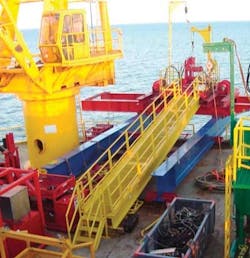
The solution began with the use of a lift boat to support the P&A operations rather than a jackup rig, due to debris on the ocean floor. To address the angled work deck, the lift boat was outfitted with a unique cantilever system and light duty work deck that extended off the side of the boat.
Instead of conventionally welding the beams and work deck in place, the cantilever system was built so it could be adjusted to match the angle of the wells. In just two weeks, a clamping system was designed to fasten the cantilever beams to the lift boat and the system was outfitted with two 50,000-lb, single-line winches. The design provided the flexibility needed to position the lift boat and complete the work.
On the first well, the P&A procedures involved mechanically cutting and pulling 10 3/4-in. casing and 16-in. casing, which was cemented into 30-in. conductor pipe. The 10 3/4-in. casing was cut using newly-developed guillotine saws. The remotely-operated, multi-string saws are self-aligning and self-clamping to minimize risk to personnel, and feature a hydraulic stabilizer to improve cutting efficiency.
When attempting to cut the 16-in. casing, it was discovered and verified by camera that the casing had parted approximately 12 ft above the mud line. The remotely-operated guillotine saw was deployed to a point approximately 20 ft above the water line to cut off the casings and facilitate entry into the wellbore.
Deployed underwater, the saw first cut the 30-in. and 16-in. casing 5 ft above the mud line. Once the sections of casing were retrieved, the loose piece of 16-in. casing was retrieved with a spear run on 3 1/2-in. drill pipe. A hydraulically-actuated mechanical cutter was then deployed on 3 1/2-in. drill pipe, the 30-in. casing was cut 15 ft below the mud line, and the remaining casing and conductor were retrieved without incident.
For the second well, the objective was to remove the crow’s nest and cut and pull 9 5/8-in. casing cemented inside 30-in. conductors. To begin the P&A operations, two abandoned pipelines were removed by divers, per (at that time) MMS rules and regulations. Once again, the guillotine saw was deployed to a point below the crow’s nest to cut off the casings and facilitate entry into the wellbore.
A hydraulically actuated mechanical cutter was then deployed on 3 1/2-in. drill pipe and the 30 x 9 5/8-in. casing was cut at 15 ft below the mud line. This section of casing and conductor was retrieved without incident.
The successful completion of the project was attributed to the timely design and mobilization of the adjustable cantilever system, the ability to work efficiently on the angled work deck, and the efficiency of the remotely operated, self-aligning, self-clamping guillotine saw.
Enhancing P&A performance
In each of these cases, a combination of advanced technology and aggressive engineering was key to providing the best solution. The development of the versatile intervention and well abandonment system, including the compact rig-less hydraulic pulling and jacking units are the basis for this capability. Integrated with a broad service resource that draws on P&A and other related capabilities, the technology has proven itself to be an enabler for the innovative, engineered solutions that are increasingly required to improve P&A performance. These enhancements are reducing costs, improving operational efficiency and strengthening safety across a full spectrum of P&A applications from the most basic to the most challenging.
Reference
1. Gulf of Mexico Decommissioning Outlook, Mark Kaiser, Louisiana State University Center for Energy Studies, Offshore, September 2010.
Offshore Articles Archives
View Oil and Gas Articles on PennEnergy.com