P.2 ~ Helical strake testing suggests path to VIV solution
View Article as Single page
Bare cylinder results
To properly assess the performance of a helical strake configuration, the bare cylinder (the cylinder without any helical strakes present) must first be examined.
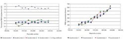
The results illustrate several things. For one, the values for adjacent accelerometers are very close; the displacement values vary with Reynolds number (i.e. test velocity) and most likely mode shape too; the accelerations increase with increased Reynolds number/test velocity which is not surprising since the mode numbers and response frequencies are increasing too; the accelerations at each end of the pipe vary, but are relatively close in magnitude indicating that very little attenuation is occurring for the bare cylinder; and the drag coefficients decrease slightly with increased Reynolds number, most likely due to an increasing portion of the cylinder length entering into the transition region for turbulent boundary layers (i.e., experiencing the well-known "drag crisis").
These bare cylinder values are useful for comparison with the straked cylinder values. The accelerations are particularly important since accelerations are directly proportional to the bending stresses that cause VIV fatigue.
Coverage length
One difficulty of designing deepwater tubulars is determining how much of the tubular to cover with VIV suppression devices. Since most deepwater areas have ocean currents that are highest in magnitude near the surface and decay in magnitude with increasing depth, this determination often focuses on how deep to cover the tubular with suppression devices, in this case helical strakes.
Cylinders were covered with 17 ft, 9 in. and 35 ft, 6 in. of helical strakes on the outer end. (Unless otherwise designated, most of the helical strakes tested herein have a 0.25D fin height and a pitch per start of 17.5D; most have three starts but some data from the second test program is for strakes with four starts, called "quad-start" helical strakes). For a 17 ft 9 in. coverage length, a reduction in displacement of about 50% was observed. However, the corresponding reduction in acceleration was far more than 50% for this same coverage level. Further, this experiment indicated a greater reduction in both displacement and acceleration at the outer (high velocity) end of the cylinder than at the inner (low velocity) end. This is due to the strong local effectiveness and damping of the helical strakes.
At the outer end, the strakes reduce the excitation tremendously and thus the vibration is quite small. However, there is still a large amount of excitation present in the bare regions of the cylinder that excite VIV. The excitation in the bare regions occurs at a lower frequency (since the excitation frequency is proportional to the flow velocity) and thus excites lower modes. Since these lower modes are exciting a system with more damping present than what was present for the bare cylinder (due to the presence of the strakes), the displacements are lower and the displacements at the inner end are lower than those on the outer end. This indicates that the helical strakes are also providing substantial local damping.
Increasing the strake coverage length from 17 ft, 9 in. to 35 ft, 6 in. had the effect of reducing the displacements at both ends of the cylinder, at the expense of a small increase in the overall drag (it is well known that helical strakes have higher drag than most non-vibrating bare tubulars, and thus it is not surprising that additional strake coverage increases the overall drag). The displacements were also lowered by the additional strake coverage, again due to increased damping introduced by the additional strakes.
In short, covering only 18.4% (17 ft, 9 in.) of the outer end of the tubular reduced the accelerations at the inner end by a factor of well over two and reduced the accelerations at the outer end by a factor of about four to six (the exact amount of reduction is dependent upon the actual test velocity/Reynolds number). A suppression efficiency of over 80% was generated at the outer end simply by covering 18.4% of the tubular with helical strakes. Covering just 36.8% (35 ft, 6 in.) of the tubular reduced accelerations at the inner end by a factor of three to eight, and at the outer end by a factor of well over 10. Presumably the reductions might be even greater if currents were not experienced by the tubular on the bare region.
In the second test program using the same setup, quad-start helical strakes were tested with a wider range of coverage lengths than what was tested in the first test program. Starting at the outer end, one, two, three, and five joints were covered with helical strakes and the results compared with the bare cylinder results (from that same test program). To provide an overall view of the results, each of the displacement, acceleration, and frequency values were averaged for all of the tests and for all of the accelerometers.
As the strake coverage length was increased, accelerations and displacements decrease. Since the strakes decrease both displacement and frequency, the acceleration values were lower than the displacement values. At a coverage density just under 80%, the strakes reduced the average accelerations by over an order of magnitude.
