P.2 ~ Subsea power, control advances extend West Delta Deep Marine network
View Article as Single page
Control systems evolution
While the overall system design has generally used proven technology, there were challenges associated with the continued development of the systems and the required instrumentation associated. These included the need to avoid hydrates, control of chemical injection, gas rate measurement, and sand detection. Initially the field was conceived as a three-phase development, with each phase being an eight-well, two-manifold configuration with a four-well, one-manifold expansion capacity. However, the pressure to maintain production levels to support Egypt's national grid and the adjacent LNG plant has driven the expansion well beyond the initial figures.
One critical consideration for the expansion was the need to supply a sufficient operating margin for the power supplies. The system initially was designed for a defined expansion. When those limits were exceeded, work was required with control system vendors to define operating scenarios and levels of instrumentation to obtain the desired field information.
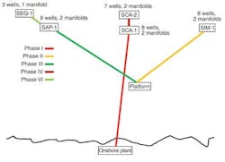
The subsea control system for phases I-III of the WDDM development had to address various technical challenges, including long-distance step‐outs, a chemical injection delivery network, gas and condensate monitoring, sand detection, and interfaces to multiple control system vendors. For Phase I Aker Solutions (formerly Kvaerner) supplied the subsea controls. The step out is nominally 90 km (56 mi) direct to shore, with communication through the vendor's proprietary protocol on a copper-based cable network. To improve the communications, signal level repeater modules were installed at the subsea distribution assembly (SDA), 82 km (51 mi) from shore.
GE Oil & Gas (then ABB Vetco Gray) supplied the Phase II and III subsea control system for a network of 16 wells and four manifolds, with the farthest well nominally 124 km (77 mi) from shore. Although a copper cable-based system may have been feasible, the lack of proven installations subsea and the need to increase local manufacturing content determined the addition of a dedicated, unmanned, controls platform 60 km (37 mi) from shore. This also increased the complexity, particularly with respect to a shore-platform link to handle all platform communication requirements, in addition to the subsea system. To maximize use of the platform, the design was formulated not just for phases II and III, but also to support later developments, including the Saurus reservoir.
The Phase IV expansion (seven wells and two manifolds), centered on additions to the Scarab/Saffron production hub and exceeded the initial design capacity of a four-well and one-manifold expansion. Moreover the requirement to acquire greater data and to control MEG injection necessitated the addition of wet gas flowmeters (WGFMs) and operator-adjusted glycol control units (GCUs), previously ROV-adjusted. A review of the original analysis confirmed that with the existing dual power supplies, the system remained functional. However, should the system be required to operate on a single power line, studies suggested it would not function because the power needed would exceed the power available. At the same time, increasing the supply voltage would not be possible as the umbilical cable rating would be exceeded.
Another issue was the inrush current that would be absorbed by the WGFMs during start-up. Typically all sensors within the subsea control module (SCM) were powered up on the application of system power, allowing data to be displayed as soon as communication was established. However, data from the WGFM is only of value once the well is flowing, and does not need to be switched on automatically when power is applied to the SCM. Therefore, the software was modified to have the WGFM "off" during power‐up, requiring the operator to actively switch the device on prior to well start. This allows the Phase I and IV equipment to operate on a single power channel by selecting only the WGFMs that are really needed.
The Phase VI Sequoia development comprised six additional wells to the existing Sapphire and Rosetta developments. The Sequoia South wells are routed to the existing subsea Rosetta infrastructure and are operated from the Rosetta control room. These wells are independent of the WDDM operation, although gas metering is crucial to define the production level.
Phase VIII originally was intended to be the final WDDM development and was initially split into three installation campaigns, "a", "b", and "c," later reduced to "a" and "b," with "c" replaced by the current Phase IXa development.
One advantage of the original premise was the requirement for simplicity and a common design approach. This meant the umbilical design and the platform-located electrical power unit (EPU), were a common design for both the Simian and Sapphire hubs, even though Sapphire was half the distance from the platform, at 24 km (15 mi), compared to Simian, at 53 km (33 mi). Routing back into the Scarab/Saffron facilities would add another 22 km (13.7 mi), bringing the maximum step out to roughly 46 km (28.5 mi), still less than the distance to Simian.
An initial vendor review of the Simian and Sapphire power system indicated scope for further expansion to accommodate Phase VIIIa requirements. This was confirmed by detailed analysis, although the results revealed that the system was at the limits of its existing design capacity, with the power transformer running at 95% of its rating, the system supply voltage approaching 98%, and the maximum SCM voltage/minimum load case being within 5% of the upper limit.
The VIIIb campaign eventually added five wells, one with a HIPPS, along with one manifold on Simian; one well on Scarab/Saffron; and two wells, one with a HIPPS, on Sapphire. However, based on the work for Phase VIIIa, it was apparent that in the single-channel case the Sapphire hub was at or potentially beyond its maximum capacity. Analysis suggested that the conventional, dual-channel supply would best to support the VIIIb needs. In addition the subsea configuration at the distribution units was revised to better distribute the supply from the incoming Sapphire umbilical.
The VIIIb expansion effectively exceeded the rating of the power transformers, with a worst-case demand of 130% of the rated output. In addition, for the single-channel case several of the higher power requirement sensors need to be switched off to maintain a suitable margin.
