Subsea power, control advances extend West Delta Deep Marine network
David Smith
INTECSEA
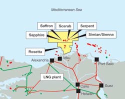
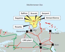
In 1999 INTECSEA (then INTEC) began a front-end engineering and design (FEED) study for the West Delta Deep Marine (WDDM) concession offshore Egypt in the Mediterranean Sea. The development was operated by the Burullus Gas Co., a joint venture among BG, state-owned EGPC, and Edison Gas, with the latter since replaced by Petronas Carigali.
This was the first deepwater development offshore Egypt, and there was little associated infrastructure to draw on at the time. The project was also pioneering as one of the longest tiebacks to shore at 90 km (56 mi), taking in the Scarab/Saffron fields via eight subsea wells and two manifolds.
INTECSEA has continued to work with Burullus on subsequent phases of the development, which has been expanded farther from shore at 105 km (65 mi), and in deeper water to 1,024 m (3,359 ft). Various services have been introduced, such as subsea electrical power, to allow expansion beyond the originally planned capacity of three hubs, each with a maximum of 12 wells, and three manifolds, to currently more than 50 wells and 12 manifolds. Further expansion is planned, including the current Phase IXa, adding potentially another 20 wells with associated manifolds.
Hydrates control
Produced gas from the WDDM fields is sweet but the pressures and temperatures are such that there is a continual risk of hydrates from the produced water. Continuous MEG injection, complete with corrosion inhibitor, is necessary and it is achieved through dedicated flow lines from the terminal to each field center. In addition, methanol injection is required at start‐up and shutdown. Depending on the development phase, chemical injection facilities are either located onshore or on a dedicated controls platform 62 km (38.5 mi) from shore.
The Sapphire field also produces a significant amount of condensate that must be extracted prior to the gas entering Egypt's National Transmission System (NTS) or the adjacent LNG plant.
The subsea pipelines are made of carbon steel with diameters ranging from 10-in. for well flowlines to 20-in. and 26-in. for infield pipelines. A pipeline end termination (PLET) is integrated to each flowline end, and includes a Cameron Vertical Connection (CVC) interface. There is provision for the flowline to slide longitudinally on the PLET foundation to allow temperature expansion and to avoid locked‐in forces that could result in flowline buckling. The infield flowlines eventually terminate at the pipeline end manifold (PLEM), where the pipeline diameters increase to 24-in. and 36-in. to provide the required export capacity to the onshore plant.
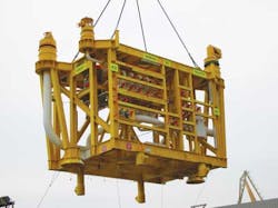
Subsea equipment includes horizontal trees, manifolds, and a remote pipeline connection system. Subsea christmas trees are the horizontal type with the flowloop connector hub mounted directly on the tree body. Remotely installed tie‐in jumper spools connect the trees to the manifolds which, like the christmas trees, are designed to suit the CVC system.
Fishing activity may occur in water depths down to roughly 200 m (656 ft), so the larger pipelines are designed for fishing gear pullover loads while the 4‐in. lines and umbilicals are trenched up to this water depth. Subsea structures in the shallower waters are designed to be overtrawlable, while in deeper waters the structures are upright. From Phase IX the requirement to protect the subsea equipment from damage has increased to 400 m (1,312 ft) water depth.
Development history
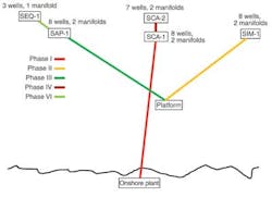
Under Phase 1, the Scarab/Saffron fields were the first to be developed via a total of eight wells connected to two production manifolds and controlled directly from the shore terminal at a distance of around 90 km (56 mi). Both fields came onstream in 2003 at around 700 MMcf./d. Twin 20-in. main export pipelines commence at a water depth of 415 m (1,361 ft) and extend for 30 km (18.6 mi) to the PLEM at a depth of 95 m (311 ft), where 24-in. and 36-in. export lines transports production to the shore terminal. A 4-in. pipeline conveys MEG from shore to the fields for hydrate inhibition via direct injection at the trees.
The Simian/Sienna (Phase II) and Sapphire (Phase III) field developments were the first expansions to provide gas to a new onshore LNG plant, with six wells at Simian, two at Sienna, and eight at Sapphire. Flows from these fields come together at the PLEM where the gas is commingled into the export pipelines to shore. The Simian wells are capable of a maximum throughput of 150 MMcf/d. All the subsea wells, in water depths beyond 1,000 m (3,281 ft), are controlled from shore through an electro-hydraulic multiplexed system, with controls, hydraulic power, and methanol injection equipment mounted on a controls platform in shallower water close to the PLEM.
Phase IV involved a seven-well and two-manifold expansion centered on the Scarab/Saffron production hub. This was followed by an investment in booster compression (Phase V) and the Phase VI Sequoia reservoir development, which comprised three wells on Sequoia North in the western flank of the Sapphire area and three more on the Sequoia South area, routed to the existing subsea Rosetta infrastructure and control room facilities.
Further pipeline capacity and main compression were added under Phase VII, at which point the continued development of WDDM required new wells to access additional reserves. Phase VIII was split into two phases, the first adding five wells and two manifolds to the Sapphire field and four wells and a single manifold to the Scarab/Saffron area. The second part added another well to the Scarab area, connected to the previously installed M6 manifold, and five wells and a manifold within the Simian area, linking three wells to the M2 manifold, with the remaining two wells "daisy chained" and connected to the remaining slot on the M1 manifold. The W37 well had an initial wellhead pressure that exceeded the rating of the Simian area pipeline and therefore was equipped with a high integrity pressure protection system (HIPPS).
Control systems evolution
While the overall system design has generally used proven technology, there were challenges associated with the continued development of the systems and the required instrumentation associated. These included the need to avoid hydrates, control of chemical injection, gas rate measurement, and sand detection. Initially the field was conceived as a three-phase development, with each phase being an eight-well, two-manifold configuration with a four-well, one-manifold expansion capacity. However, the pressure to maintain production levels to support Egypt's national grid and the adjacent LNG plant has driven the expansion well beyond the initial figures.
One critical consideration for the expansion was the need to supply a sufficient operating margin for the power supplies. The system initially was designed for a defined expansion. When those limits were exceeded, work was required with control system vendors to define operating scenarios and levels of instrumentation to obtain the desired field information.
The subsea control system for phases I-III of the WDDM development had to address various technical challenges, including long-distance step‐outs, a chemical injection delivery network, gas and condensate monitoring, sand detection, and interfaces to multiple control system vendors. For Phase I Aker Solutions (formerly Kvaerner) supplied the subsea controls. The step out is nominally 90 km (56 mi) direct to shore, with communication through the vendor's proprietary protocol on a copper-based cable network. To improve the communications, signal level repeater modules were installed at the subsea distribution assembly (SDA), 82 km (51 mi) from shore.
GE Oil & Gas (then ABB Vetco Gray) supplied the Phase II and III subsea control system for a network of 16 wells and four manifolds, with the farthest well nominally 124 km (77 mi) from shore. Although a copper cable-based system may have been feasible, the lack of proven installations subsea and the need to increase local manufacturing content determined the addition of a dedicated, unmanned, controls platform 60 km (37 mi) from shore. This also increased the complexity, particularly with respect to a shore-platform link to handle all platform communication requirements, in addition to the subsea system. To maximize use of the platform, the design was formulated not just for phases II and III, but also to support later developments, including the Saurus reservoir.
The Phase IV expansion (seven wells and two manifolds), centered on additions to the Scarab/Saffron production hub and exceeded the initial design capacity of a four-well and one-manifold expansion. Moreover the requirement to acquire greater data and to control MEG injection necessitated the addition of wet gas flowmeters (WGFMs) and operator-adjusted glycol control units (GCUs), previously ROV-adjusted. A review of the original analysis confirmed that with the existing dual power supplies, the system remained functional. However, should the system be required to operate on a single power line, studies suggested it would not function because the power needed would exceed the power available. At the same time, increasing the supply voltage would not be possible as the umbilical cable rating would be exceeded.
Another issue was the inrush current that would be absorbed by the WGFMs during start-up. Typically all sensors within the subsea control module (SCM) were powered up on the application of system power, allowing data to be displayed as soon as communication was established. However, data from the WGFM is only of value once the well is flowing, and does not need to be switched on automatically when power is applied to the SCM. Therefore, the software was modified to have the WGFM "off" during power‐up, requiring the operator to actively switch the device on prior to well start. This allows the Phase I and IV equipment to operate on a single power channel by selecting only the WGFMs that are really needed.
The Phase VI Sequoia development comprised six additional wells to the existing Sapphire and Rosetta developments. The Sequoia South wells are routed to the existing subsea Rosetta infrastructure and are operated from the Rosetta control room. These wells are independent of the WDDM operation, although gas metering is crucial to define the production level.
Phase VIII originally was intended to be the final WDDM development and was initially split into three installation campaigns, "a", "b", and "c," later reduced to "a" and "b," with "c" replaced by the current Phase IXa development.
One advantage of the original premise was the requirement for simplicity and a common design approach. This meant the umbilical design and the platform-located electrical power unit (EPU), were a common design for both the Simian and Sapphire hubs, even though Sapphire was half the distance from the platform, at 24 km (15 mi), compared to Simian, at 53 km (33 mi). Routing back into the Scarab/Saffron facilities would add another 22 km (13.7 mi), bringing the maximum step out to roughly 46 km (28.5 mi), still less than the distance to Simian.
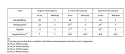
An initial vendor review of the Simian and Sapphire power system indicated scope for further expansion to accommodate Phase VIIIa requirements. This was confirmed by detailed analysis, although the results revealed that the system was at the limits of its existing design capacity, with the power transformer running at 95% of its rating, the system supply voltage approaching 98%, and the maximum SCM voltage/minimum load case being within 5% of the upper limit.
The VIIIb campaign eventually added five wells, one with a HIPPS, along with one manifold on Simian; one well on Scarab/Saffron; and two wells, one with a HIPPS, on Sapphire. However, based on the work for Phase VIIIa, it was apparent that in the single-channel case the Sapphire hub was at or potentially beyond its maximum capacity. Analysis suggested that the conventional, dual-channel supply would best to support the VIIIb needs. In addition the subsea configuration at the distribution units was revised to better distribute the supply from the incoming Sapphire umbilical.
The VIIIb expansion effectively exceeded the rating of the power transformers, with a worst-case demand of 130% of the rated output. In addition, for the single-channel case several of the higher power requirement sensors need to be switched off to maintain a suitable margin.
Phase IX
At the completion of Phase VIII the system had effectively been expanded beyond its practical design limit, with sensors needing to be "disconnected" to maintain operation using a single power channel on both the Simian and Sapphire hubs. Also, the earlier Phase IV expansion had exhausted all available capacity of the shore-based Aker Solutions control system. To further expand the system to accommodate potentially another 16 wells, nine HIPPS, and one manifold, all distributed across the Simian, Scarab/Saffron, and Sapphire areas, a significant reassessment and system upgrade would be needed.
The conceptual stage examined options for expanding the control system, including a control buoy; high voltage power supply (< 1kV AC); a new control system; and a new umbilical to the platform or directly to shore.
A control buoy would provide the significant benefit of a relatively short length of electrical umbilical by locating the buoy directly above the system tie-in point. This would minimize both the cost and voltage drop of the main umbilical. However, the cost of a control buoy system would be substantial, and interfacing this with the existing control system would require significant modifications to existing hardware/software interfaces. Further, there was the question of reliable communications, either over a satellite link or an additional, dedicated communication umbilical to shore.
The introduction of a high voltage – greater than 1kV AC – three-phase system represented a significant technical change to the existing philosophy and was deemed too great a risk in terms of integration with existing assets and technical complexity. Therefore, a single-phase solution remains the best case for power transmission.
A new shore-based umbilical would be costly due to the long offset required, and would also require a new shore-based control system. In addition, it potentially "splits" the control of an area across two master control stations involving extra interfacing, and would not resolve the power limitation of the existing system.
A new umbilical from the Simian controls platform would allow the full expansion of Phase IX by providing the flexibility to balance existing system loading and to use the EPU channels originally dedicated to Saurus, which remain unused following a power cable failure on Sapphire. Maintaining the original supply voltages also would allow the provision of inter-field umbilicals to better distribute power between the fields, with a large cross-section to provide capacity for further expansion.
With all options, the costs are significant. However, the introduction of a new main umbilical from the controls platform is the route taken for Phase IX due to the easier integration with existing systems and more straightforward future expansion.
The current Phase IXa, which came onstream in summer 2014 and which is still under construction, involves adding nine wells, six HIPPS, and one manifold to the Simian and Scarab, and Sapphire areas. The campaign includes installation of a J-tube and associated topsides equipment, upgrading the power transformers, and installing a new umbilical to the Scarab area. From there, infield umbilicals will distribute additional power to the Sapphire and Simian hubs to support the new wells, HIPPS, and manifolds, along with the existing equipment. The system is designed to be suitable for the IXb campaign and beyond, with potential for further expansion of the WDDM subsea architecture.
The onshore plant can process 2 MMcf/d of gas, and there will always be a driver to maintain this limit. Therefore, studies are underway to connect the Libra and Taurus fields, part of the BP West Nile Delta concession, to the current pipeline network. This will enable the onshore plant to maintain plateau production and also allow these fields to be brought onstream without having to build additional onshore capacity.
From a control system perspective, these fields will require a complete new control system, which, after conceptual study, will be from the platform. Modifications to the platform will increase not only the control system capacity, but also the chemical injection capability as an additional J‐tube being installed to allow a dedicated umbilical to support the Libra‐Taurus development, and possibly more.
Acknowledgments
Based on a paper presented at the Deep Offshore Technology International Conference & Exhibition held in Aberdeen, Scotland, October 14-16, 2014.