p.2 ~ Variable frequency drive power may bolster subsea production technology
View Article as Single page
Manufacturing challenges
The manufacturing of onshore cables is straight-forward. The short production length (typically a drum length) enables moving the cable between production steps on drums until the final layer has been applied and the cable drums can be put to the final acceptance test.
Submarine power cables, to the contrary, often are shipped in extreme lengths limited only by the capacity of the cable-laying vessel. This can be several thousand tons of cable. To avoid a large number of joints, all production steps are done on lengths as long as possible. The maximum continuous production length of each production step depends on the cable size and type. More often than not, the production lengths of the different steps cannot be harmonized completely. This results in an intricate planning of the use of production assets. Only a well-orchestrated factory can exploit the advantage of long shipping length.
Because electrical conductors usually are manufactured in lengths much shorter than the total length required for the finished power cable, conductor splices are typically required. Flexible conductor splices are common and must be flush with the cable conductor. After the conductor connection is made, the insulation of each adjacent cable end is tapered. The gap is filled with lapped XLPE tapes, and then cured under heat and pressure. The added insulation melts together with the surface of the tapered cable insulation. Some factories produce injection-molded factory joints. Joint flexibility is crucial for the subsequent travel of the cable core through the cable gantries of the factory.
Gaseous byproducts dissolved in the XLPE matrix must be removed. If not degassed properly, the cables emit these gases during operations, resulting in unwanted gas volumes in the conductor. Degassing of long lengths of submarine cable cores requires large heated and ventilated vessels.
Traditionally, radial water barriers were lead sheaths. The lead sheath for submarine power cables is applied with a lead press, or an extruder in uniform thickness of 2 -5 mm. Long-term stability, creep, and extrusion properties can be improved using lead alloys with alloy elements such as antimony, tin, copper, calcium, cadmium, tellurium, and others. In some cases the sheath is copper. More recently, a move away from lead has seen fostered by the application of a copper strip folded longitudinally around the cable, with the edges trimmed and welded continuously. Then the formed copper tube is corrugated to increase the flexibility.
Leibfried suggest a more sophisticated control topology is required for ASMs on longer cables, namely a Closed Loop Rotation Speed Controller. This system provides perfectly stable results for different cable lengths and load conditions as well as for load changes. However, it requires information about the actual values of stator current and rotation speed of the asynchronous motor, and this complicates the design.
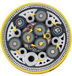
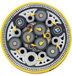
Umbilical manufacture
Stolan offered a solution to the closely coupled three-phase circuit induced parasitic voltage phenomena. The solution consists of using opposite lay directions to the three-phase power circuits. Looking at two different cable circuits, the length of each cable is equal to one helix height. In one cable, only the inner circuit is twisted. When applying asymmetrical three-phase AC current to one circuit, a net magnetic field will rotate with the same frequency as the applied current. Looking at the cross-section of either cable, it would seem that the conductors are parallel at a length into the plane. The rotating magnetic field would then induce a potential voltage difference over the length of a second conductor. If the conductors are twisted, the induced potential difference between the two conductors is a function of the sum of the magnetic field over one period, equal to zero. At any point in time, the second conductor experiences the entire period of the magnetic potential, canceling out the potential difference of the conductors over one exact helix length.
By twisting both circuits in opposite directions, the net induced voltage cancels out over half a helix height. In particular, manufacturing both circuits with opposing lay directions in the cable is straightforward as it affords opposing lay directions on two different layers.
Achieving an exact balance between cable inductive reactance and capacitive reactance by design is not reasonable, but the subsequent interaction of the two marginally increases overall power through-put capacity and size of the associated reactive compensation network for the outer layer. Detailed reactive power analysis and compensation design will determine the benefit for a given installation.
Inline conductor splices
Inline conductor splices can greatly enhance the manufacturable length of a submarine power cable and are reliable and repeatable as long as the gaseous byproducts that are dissolved in the XLPE matrix are removed. If not degassed properly, the cables emit these gases during operation later, on resulting in unwanted gas volumes in the conductor. The degassing of long lengths of submarine cable cores requires large heated and ventilated vessels.
Looking at the opposing lay dual circuit three-phase HV power cable, the twisted quads are subject to the aforementioned induced voltage stress phenomena, and this needs to be addressed on longer submarine power cables due to the cumulative nature of induced voltages. However, provision of input and output transformer isolation for each communication circuit will mitigate these adverse effects and prolong insulation life. Detailed analysis is recommended if fiber-optic communications are not employed.
Editor's note: The foregoing is excerpted from a presentation at the Deep Offshore Technology International Conference and Exhibition held in The Woodlands, Texas.