Variable frequency drive power may bolster subsea production technology-full
Richard Voight
INTECSEA Inc.
Subsea equipment that works on produced fluid to enhance, enable, and/or prolong reservoir life has a bright future. As subsea active production technology (SAPT) matures, so will the technology to regulate, transmit, and connect electrical power to SAPT loads. Subsea variable frequency drive (VFD) technology is on the horizon and promises to mitigate unstable long-distance control issues and to enable efficient and cost-effective subsea distribution networks.
The drivers for longer and deeper subsea tiebacks also drive the evolution of SAPT and its associated equipment. In particular, submarine power cables servicing SAPT loads combine multiple functions to reduce umbilical capex and installation costs, but this detrimentally affects induced voltages between closely coupled power and communications circuits. However, careful consideration to these at the design stage can mitigate these issues with little or no impact to manufacturing and/or overall transmission line complexity.

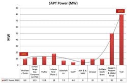
SAPT is the primary driver for considering long-distance subsea power transmission (LDSPT) when developing a subsea field. A growing number of projects employ some form of SAPT. Integrated systems can require lots of power. Subsea boosting and/or caisson separation pumps can easily reach 3 MW each; with multiple pump installations quickly adding a substantial demand on a host facility. Subsea compression loads are even more demanding and can reach 40 MW for a single compressor.
Adding subsea boosting to a brownfield can boost mid- to late-life production resulting in increased overall production and reduce the lifecycle, thereby improving development economics. The theoretical impact of subsea boosting suggests production can be increased throughout the field lifecycle to significantly increased production and improved development economics.
The typical subsea methods of adding energy to produced fluids include:
- Pumping – liquids and multi-phase
- Compression – Dry gas and multi-phase
- Separation – Two- and three-phase plus sand
- Local produced water and seawater injection
- Electrically heated flowlines.
The only form of SAPT that does not require external input power (excluding control power) is separation. Separation draws on energy from the produced fluid in the form of hydraulic power (flow x pressure drop). All remaining forms of SAPT require externally applied power.
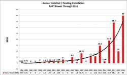
SAPT power requirements
Installed or pending installation SAPT power requirements are substantial and are envisioned to grow as the technology matures and gains acceptance. INTECSEA estimates an installed or pending installation total subsea power requirement approaching 330 MW. The future demand for SAPT power is striking when one combines the annual installed / pending installation total estimated power requirement through 2016.
Power over long distances
Subsea tiebacks (STBs) to existing hosts have enabled numerous subsea field developments that would not be economically viable otherwise. The subsea tieback has become a global staple. Maturation of the technology makes possible longer and longer step outs in increasing water depths. Longer step outs distances create new challenges for submarine cables. Where STBs were typically less than 10-15 km (6.2-9.3 mi), current developments exceed 40 km (25 mi) with some at 100 km (62 mi). In addition to increasing step out distances, subsea developments are going into deeper and deeper water. The depth challenges are self-evident and serve to add an additional layer of challenges in addition to increasing tieback distances.
A key limit of all AC cables is their high electrical capacitance. For longer lengths of cable the capacitive charging current becomes significant and results in a reduction in the ability to transmit real power. It is very expensive offshore to install compensation mid-route. That requires additional platforms. The negative effect of cable charging currents increases with increasing voltage. Therefore, as voltage levels are increased to achieve higher cable power capacities, effective transmission distances are reduced.
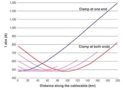
The compensation network point of connection significantly impacts the maximum current loading within a cable. For the case of single end reactive compensation, applied to different cable lengths, minimum current appears at the end opposite to the reactive compensation network, with the maximum current appearing at the shunt reactive network point of connect. On the contrary, with a compensation of 50% of the reactive power at each end, the minimum current appears in the middle of the cable and the maximum currents at both ends. For 36 kV or 150 kV, the maximum current cable load is reduced significantly by application of reactive power compensation networks at both ends.
This reduction and current distribution pattern along the cable happens for all the cable lengths and all the configurations. The different configurations and the different cable properties only impact the amount of the generated reactive power, not in the maximum current reduction or in the distribution of the current along the cable.
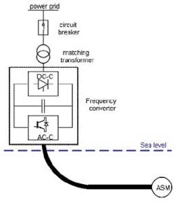
Asynchronous motor regulation
Leibfried, et al detail motor starting issues associated with asynchronous machines (ASM) (induction motors) at the end of long cable lengths (on the order of kilometers). In that analysis, the system was analyzed for both short and long cable lengths to the ASM. Leibfried also notes anticipated issues associated with traveling waves due to switching operations of the IGBT's inside the frequency converter can result in high overvoltages on the motor side of the cable.
Leibfried steady-state results show stable system behavior for both short and long cable lengths, however when a simplified V/Hz control is applied during transient states, there are no issues with starting associated with shorter lengths of cable, but the ASM fails to start with long lengths of cable.
In electromagnetism and electronics, inductance is the property of a conductor by which a change in current in the conductor "induces" (creates) a voltage (electromotive force) in both the conductor itself (self-inductance) and in any nearby conductors (mutual inductance). Parasitic induced voltages in nearby conductors can cause problems for communication circuits as well as for closely coupled low- and high-voltage power circuits.
Slater et al examined the electromagnetic fields surrounding an individually shielded triaxial AC cable which exhibits similar construction to a typical three-phase SAPT power cable. Both the magnetic field is reduced with the triaxial cable compared to the single-phase cable for distances greater than 0.4 m (1.3 ft) from the cable axis. However, less than 0.4 m from the axis, the three-phase cable generates magnetic fields higher than those produced at the same distance from a single-phase cable carrying the same current.
This is significant when multiple three-phase power circuits are integrated into a single SAPT power service umbilical due to the closely coupled nature of the umbilical assembly. The distances between adjacent circuits are significantly less than the 0.4 meter threshold, so parasitic induced voltage must addressed, quantified, and possibly mitigated during design.
M. B. C. Salles et al presented an adopted way to evaluate cable performance as a combination of 2D-finite element analyses (coupled with electric circuit) and the transposition technique to reduce the need for complex 3D FEA models.
In addition to motor related issues, and in the event twisted pairs (TPs) or twisted quads (TQs) are integrated into the power cable assembly, challenges arise in the form of added voltage stress from the mutual inductance between the power circuits and the closely coupled communications circuits (TPs/TQs). Cross-talk should not be an issue because of the frequency separation between the power circuits and the communications circuits. Input and output transformer isolation for each communications circuit will mitigate this and prolong insulation life.
Manufacturing challenges
The manufacturing of onshore cables is straight-forward. The short production length (typically a drum length) enables moving the cable between production steps on drums until the final layer has been applied and the cable drums can be put to the final acceptance test.
Submarine power cables, to the contrary, often are shipped in extreme lengths limited only by the capacity of the cable-laying vessel. This can be several thousand tons of cable. To avoid a large number of joints, all production steps are done on lengths as long as possible. The maximum continuous production length of each production step depends on the cable size and type. More often than not, the production lengths of the different steps cannot be harmonized completely. This results in an intricate planning of the use of production assets. Only a well-orchestrated factory can exploit the advantage of long shipping length.
Because electrical conductors usually are manufactured in lengths much shorter than the total length required for the finished power cable, conductor splices are typically required. Flexible conductor splices are common and must be flush with the cable conductor. After the conductor connection is made, the insulation of each adjacent cable end is tapered. The gap is filled with lapped XLPE tapes, and then cured under heat and pressure. The added insulation melts together with the surface of the tapered cable insulation. Some factories produce injection-molded factory joints. Joint flexibility is crucial for the subsequent travel of the cable core through the cable gantries of the factory.
Gaseous byproducts dissolved in the XLPE matrix must be removed. If not degassed properly, the cables emit these gases during operations, resulting in unwanted gas volumes in the conductor. Degassing of long lengths of submarine cable cores requires large heated and ventilated vessels.
Traditionally, radial water barriers were lead sheaths. The lead sheath for submarine power cables is applied with a lead press, or an extruder in uniform thickness of 2 -5 mm. Long-term stability, creep, and extrusion properties can be improved using lead alloys with alloy elements such as antimony, tin, copper, calcium, cadmium, tellurium, and others. In some cases the sheath is copper. More recently, a move away from lead has seen fostered by the application of a copper strip folded longitudinally around the cable, with the edges trimmed and welded continuously. Then the formed copper tube is corrugated to increase the flexibility.
Leibfried suggest a more sophisticated control topology is required for ASMs on longer cables, namely a Closed Loop Rotation Speed Controller. This system provides perfectly stable results for different cable lengths and load conditions as well as for load changes. However, it requires information about the actual values of stator current and rotation speed of the asynchronous motor, and this complicates the design.
Umbilical manufacture
Stolan offered a solution to the closely coupled three-phase circuit induced parasitic voltage phenomena. The solution consists of using opposite lay directions to the three-phase power circuits. Looking at two different cable circuits, the length of each cable is equal to one helix height. In one cable, only the inner circuit is twisted. When applying asymmetrical three-phase AC current to one circuit, a net magnetic field will rotate with the same frequency as the applied current. Looking at the cross-section of either cable, it would seem that the conductors are parallel at a length into the plane. The rotating magnetic field would then induce a potential voltage difference over the length of a second conductor. If the conductors are twisted, the induced potential difference between the two conductors is a function of the sum of the magnetic field over one period, equal to zero. At any point in time, the second conductor experiences the entire period of the magnetic potential, canceling out the potential difference of the conductors over one exact helix length.
By twisting both circuits in opposite directions, the net induced voltage cancels out over half a helix height. In particular, manufacturing both circuits with opposing lay directions in the cable is straightforward as it affords opposing lay directions on two different layers.
Achieving an exact balance between cable inductive reactance and capacitive reactance by design is not reasonable, but the subsequent interaction of the two marginally increases overall power through-put capacity and size of the associated reactive compensation network for the outer layer. Detailed reactive power analysis and compensation design will determine the benefit for a given installation.
Inline conductor splices
Inline conductor splices can greatly enhance the manufacturable length of a submarine power cable and are reliable and repeatable as long as the gaseous byproducts that are dissolved in the XLPE matrix are removed. If not degassed properly, the cables emit these gases during operation later, on resulting in unwanted gas volumes in the conductor. The degassing of long lengths of submarine cable cores requires large heated and ventilated vessels.
Looking at the opposing lay dual circuit three-phase HV power cable, the twisted quads are subject to the aforementioned induced voltage stress phenomena, and this needs to be addressed on longer submarine power cables due to the cumulative nature of induced voltages. However, provision of input and output transformer isolation for each communication circuit will mitigate these adverse effects and prolong insulation life. Detailed analysis is recommended if fiber-optic communications are not employed.
Editor's note: The foregoing is excerpted from a presentation at the Deep Offshore Technology International Conference and Exhibition held in The Woodlands, Texas.