DEEPWATER DRILLING & PRODUCTION J-Laying deepwater pipelines with drillship and threaded connections
Jim Sikes
Sonat Offshore DrillingJoe Roche
Hydril Company
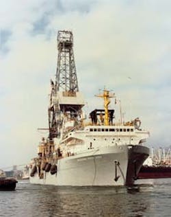
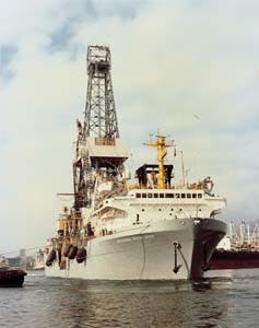
Drillships such as Sonat's Discoverer Seven Seas can be equipped to lay pipe in deep water with minimum alteration.
Traditional methods of laying offshore pipelines using S-Lay cannot be practically used in deep water. The tortuous S-Lay configuration is characterized by high bending and tensile loads at the top of the pipe span. These loads are amplified as water depth increases, consequently inducing stresses beyond the pipe material allowable limits.
Pipelaying operations can be extended to deeper water by employing J-Lay. This paper proposes that a DP (dynamically positioned) drillship using threaded (rather than welded) joining is the ideal solution.
A DP drillship has a high deck loading pipe capacity and accurate positioning. A threaded connector with metal to metal seals allows fast make-up and reliable long term pressure containment.
Specifically, the DP drillships described here are Sonat Offshore Drilling's Discoverer 534 and Discoverer Seven Seas deepwater floaters. The pipeline connector is Hydril Company's Series 2000 coupled threaded connector.
As offshore oil and gas producing operations move into deeper water locations, greater demands are being placed on pipeline installers. In particular, the commonly used S-Lay method of laying pipe on the sea floor is limited by excessive stress in the suspended pipe and therefore can not be used beyond certain depths, depending on pipe strength. Combined high tensile and bending loads on the pipe as it exits the laybarge stinger are induced by the large hanging weight and the necessity for the pipe to experience tortuous bending from horizontal to approaching vertical to horizontal attitude.
A ready way to increase the water depth utility for any pipe size is to employ the J-Lay method. This configuration reduces the stress at the top of the suspended pipe string by effectively eliminating bending at the top and by shortening the unsupported span. This method also eliminates the need for tensioning devices which are used in S-Lay to avoid pipe structural failure.
Shipshape vessels are ideal for J-Laying chiefly because of their high capacity to carry pipe. A DP drillship is best suited for maintaining accurate position control. These vessels are naturally equipped to efficiently make-up high strength threaded connections.
When J-Laying pipe, the connections are usually made one at a time, handling each successive joint to the vertical position and connecting it to the upper end of the hung-off string. This aspect further enhances the advantage of a threaded connector over welding - the joint cycle time is significantly faster using a threaded connector.
Drillships
The practical water depth limit of S-Lay techniques was previously thought to be about 1,500 ft. Larger lay barges were constructed to extend this limit out to about 2,500 feet. At such a water depth, it is very difficult and time consuming to continuously reposition the spread mooring system. This activity can pace the pipe lay rate.
A lay vessel could be dynamically positioned, but very high power levels would be required to develop the required horizontal forces. If, for any reason the DP system failed, even momentarily, the pipe would buckle at the tip of the stinger and possibly be lost. This concern was perceived by engineers more than twenty years ago and the J-Lay technique was developed.
If a DP vessel is used, it eliminates a mooring system and several expensive anchor handling boats. Then, within the pipe tensile capacity, the only practical limit for water depth is the gross lifting capacity of the derrick and drawworks that would be used to lower the pipe as it is being J-Laid. Sophisticated dynamically positioned drillship such as the Sonat Discoverer 534 or the Discoverer Seven Seas are ready-made candidates to lay pipelines in deep water with only minor modifications. Since these two drillships have a derrick capacity of 665 tons, pipe may be laid in a water depth of 6000 ft or more.
These two drillships have logged every deepwater drilling record since 1976. The D-534 drilled its first record well in 2,628 ft of water for Esso Thailand in 1976. Since then, these two rigs have surpassed their previous records many times. In 1987, the DSS drilled its last record well for Shell in the Gulf of Mexico in 7,520 ft of water. That record has not yet been surpassed. The D-534 drilled its deepest well for Amoco in the Gulf of Mexico in 6,521 ft of water.
Pipe handling
The line pipe will be fully prepared onshore off the critical path before it is transported offshore. The following processes may be completed on shore:
- Receive and inspect line pipe
- Cut Series 2000 thread profile on selected joints of pipe
- Grit blast and coat
- Double or triple joint the pipe by butt welding and NDT the welds
- Install anodes
- Install buckle arrestors (if needed)
- Perform final inspection of the finished multi-joint pipe length, number the joints, compile documentation.
Supply boats or barges will then transfer the fully prepared pipe to the drillship. 5,200 kips of double jointed line pipe may be stored in four pipe racks onboard the drillship. These joints may then be transferred to the forward existing catwalk or the aft proposed catwalk where the pipe is raised to vertical, joined at drill floor level, and run through the moonpool.
Dynamic positioning
The DP and power systems on these two vessels have been continually improved and refined over their combined 42 years of service. Once the proper position reference system is determined for a particular area of operation, the DP system may have to be modified to accept this position reference and track along the pipelay route.
The DP system can maintain more accurate position if it can drive at a very low resultant force against the pipe being laid. The magnitude of this force could be on the order of only 10-20 kips, and in the direction of the pipelay route. These vessels will weathervane the bow into the direction of the environmental forces (as they do in the drilling mode) to minimize rig motions and fuel consumption while enhancing the rig's stationkeeping ability. The DP system will allow the vessel to advance along the pipelay route regardless of the bow heading. This is a very important attribute to minimize weather downtime.
Pipe support, guidance
A proper support and guidance system must be installed on the drill floor and in the drilling moonpool to support the pipe and provide horizontal guidance during moderate vessel excursions.
The upper centering device is designed to support the weight of the suspended pipe hanging below the rig. A buckle arrestor or load shoulder could be provided on the pipe end to avoid the use of rotary slips along the length of the pipe body.
The intermediate guide is equipped with hydraulic cylinders designed to displace the pipe in any direction in the horizontal plane to ensure proper alignment to the joint being stabbed into the connector above.
The lower guide is a passive bumper, but also of great importance. Television cameras monitor the position of the pipe with respect to this lower guide. The DP system operator can then make fine adjustments to ensure that the pipe is standing away from this bumper. This practice prevents any excessive stresses from being imparted into the pipe by the vessel.
Pipe design
The pipe strain must be considered at the remaining sag bend where the pipe lays over from vertical to horizontal at the ocean floor. No buckle will occur if the proper pipe diameter to pipe wall thickness ratio is used. This ratio is generally calculated to be a maximum of about 20:1.
The minimum water depth limit will be about 400 pipe diameters. This allows the pipe to lay a full 90 over from the vertical to the horizontal at the ocean floor without imparting horizontal forces at the top of the pipe at the sag bend. To lay pipe in less than 400 pipe diameters, a modified J-Lay or conventional S-Lay technique may be used.
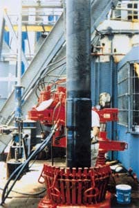
The threa-ded pipe connector is shown in shrink wrap ready to lower through the moon pool.
Threaded joint makeup
A three step system ensures a pressure tight make-up as the pipe is being run:
- Use thread protectors until the joint is positioned for make-up. Remove thread protector and use a powered thread lubricant applicator to ensure that the correct amount of lubricant is evenly applied to the threads.
- Use a joint analyzed torque make-up system to ensure that the correct amount of torque has been transferred to preload the connection. This system provides a joint-by-joint permanent record of the torquing characteristics of each joint.
- Use a fast, accurate helium leak-check system to ensure that no leak across the seal is present.
Threaded connectors have a time advantage over welding of pipe segments. The attached running time comparison chart summarizes the anticipated time cycles for both techniques. The "conservative" welded pipe time cycle is based on manual welding and radiography. The "fastest" welded pipe time cycle is based on semi-automatic welding and computer-based automatic ultrasonic testing. The threaded pipe time cycle, based on automated make-up, is clearly faster.
If deepwater development costs can be reduced, more activity will result. Drillships are well suited for deepwater, remote locations, and marginal fields. Mobilization costs are low and anchor handling boats are not required.
Minimal rig modification time and costs are required. The rig can easily convert from drilling to pipelay. Rig crews are accustomed to working with threaded tubulars.
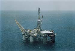
Threaded connectors have been used on the oil and gas export risers on this floating production system in the US Gulf of Mexico.
Riser service
In 1993, the American Gas Association conducted tests to evaluate the suitability of available connector designs for J-Laying. That led to the adaptation of Reflange's connector design to a R/H-L/H coupled connection employing Hydril premium threads. The seal ring and locking lugs of that design, refined by finite element techniques are allied with a Hydril MAC-II thread profile in Hydril's Series 2000 Connector.
The Series 2000 connector was put in service in July 1995 as a part of export riser lines on a floating production facility in the Gulf of Mexico. Deployed in 2,190 feet of water, the oil export riser is 12 3/4-in. O.D. and the gas export riser is 8 5/8-in. O.D. Other riser applications are being planned.
The unique features of the Series 2000 connector render it ideal, not just for J-Lay installations, but also for S-Lay, over land, and some downhole applications. However, the features of Series 2000 that best lend it to the demands of J-Laying include:
- Attractive day-rate rigs: Rigs that handle and make-up threaded pipe joints are generally available at lower day-rates than laybarges using welding techniques.
- Faster lay rates: The quick make-up and test of the Hydril Series 2000 improves installed length per day.
- Equipment savings: High cost, labor intensive, time-consuming welding and inspection equipment are eliminated.
- Mobilization cost reduction: Floating drilling rigs are available virtually wherever significant offshore reserves are found. Mobilization and conversion costs can be minimal.
- Reduced labor cost: Support personnel are fewer. Qualified welders are expensive.
- Safety: The noxious products of welding and the hazards of associated x-ray inspection are eliminated.
- Pipe choices: The Hydril Series 2000 male threads are cut directly on the seamless or seam welded pipe. Any pipe material specifications can be accommodated.
- Corrosion resistant alloys: The Series 2000 connector can join pipe made of high strength, non-weldable materials. This enables the use of corrosion resistant alloys and can eliminate expensive coatings.
- No welding: Enables a wider selection of pipeline materials.
- Facilitates handling: The coupling shoulder may be used for support during joint handling or running of pipe.
- Fast deployment: The two-step MAC-II cylindrical hooked threads provide easy stabbing (including long joints of pipe) and fast engagement (four thread wraps per revolution of the coupling).
- Readily tested:During pipe laying operations, the Series 2000 seal can easily be tested by internal and/or external pressure, or by the use of external sensors.
- Disconnectability: The Series 2000 make-up procedure can be reversed if necessary to break out a connection and keep a joint out of service.
- Positive torsional lock: The high-strength lugs at the ends of the Series 2000 pins interlock to avoid loosening of the connection caused by torque in the installed pipeline. Such torque may be a byproduct of installation or result from thermal expansion or upheaval buckling.
- Integral male threads: The Series 2000 male threads are machined on non-upset plain-end pipe which saves cost.
- Fatigue resistance: The Series 2000 connector is designed to endure fatigue induced in riser or span applications where welds may be short-lived.
- Variety of sizes: The Hydril Series 2000 connector suits a wide range of pipe sizes and ratings and can be custom-tailored for special applications.
- Buckle arresting: The Series 2000 coupling may serve as a pipeline buckle arrestor if needed.
- Piggability: Series 2000 designs have no internal upset so that the pipelines are piggable.
Prototype Series 2000 Connectors have been manufactured and tested in conjunction with the Oman to India J-Lay pipeline project and for S-Lay prospects in a cooperative effort with Oceaneering.
The Deepstar CTR 600 committee has funded an ongoing JIP to test Series 2000 connectors for deepwater J-Lay applications in the Gulf of Mexico.
Sonat's deepwater drillships and Hydril's Series 2000 connectors represent a cost and time saving alternative to conventional laybarges using welding. This combination can facilitate installations in deeper waters and enable the use of non-weldable corrosion resistant alloy pipeline materials.
This paper will be presented in longer form at the 8th Deep Offshore Technology Conference & Exhibition in Rio de Janeiro at the end of this month. Further information on this conference appears in the following article.
Copyright 1995 Offshore. All Rights Reserved.


