Proper DP system configuration ensures redundancy concept succeeds

Effective decision support tools help prevent errors
Rupert Bambach
Noble Denton marine services, part of DNV GL - Oil & Gas
For dynamically positioned (DP) vessels in the offshore oil and gas industry, the concept of redundancy is fundamental in reducing the risk of loss of position following equipment failures. However, DP vessel station-keeping incidents continue to occur because the redundancy concept fails to deliver the protection that is expected. Key amongst the possible causes of these failures is poor configuration of critical DP systems. The revised International Maritime Organization (IMO) guidance MSC Circ 1580 may, however, raise awareness of the role of good decision support tools in preventing configuration errors.
The simple principle behind a vessel’s redundancy concept is the provision of multiple separate and independent groups of equipment, each group able to independently maintain vessel position. Configuration errors represent ineffective division between redundant groups allowing failure effects to propagate from one group to another.
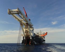
For DP vessels in the offshore oil and gas industry, there are often high risks associated with loss of position. (All images courtesy DNV GL)
The boundaries of redundant groups are most often defined by their power distribution. Physical compartment boundaries are only important for DP Class 3 vessels. The key elements of an effective redundant system include:
• Separation between redundant groups to remove potential paths for fault transfer
• Independence of equipment in each group to remove common cause vulnerabilities
• Autonomy in control systems in each group; distribution of controllers rather than centralization
• Differentiation between redundant systems to provide alternative principles for delivering functions.
In an ideal design, there should be no configuration options that can defeat the redundancy concept (other than failing to operate necessary equipment).
Ideal redundant designs may be incompatible with classification society rules (unrelated to DP) which require a vessel to have the flexibility to cross-connect critical systems to minimize loss of capability in an emergency. Additionally, ship owners may want flexibility in configuration for reasons of economy when redundancy is not required. As a consequence, most redundant designs include a network of potential cross-connections or common points offering flexibility but with the unintended consequence of introducing fault propagation paths that can defeat the redundancy concept and result in loss of position.
DP position reference systems are recognized as being particularly vulnerable to common cause failures if differentiation is not provided.
Separation
Each of the key elements of a redundant system may be compromised by poor configuration choices. Clarity in the division, or separation, of redundant equipment makes it less likely that unforeseen dependencies may lead to failure propagation from one group to another.
For instance, cross-connections in the power distribution system carry the risk of fault transfer between redundant groups, and it is widely recognized that the safest configuration is to have bus-ties open in AC distributions. DP incidents involving vessels using closed bus configuration show that many do not have the necessary protective functions to ensure fault tolerance.
Often unrecognized are cross-connections between control power sources in different redundant groups. Most standard 24VDC designs for redundant equipment include vulnerabilities that require specific configuration to mitigate the risks.
Power from multiple redundant groups may be provided to equipment as a back-up or continuous dual supply. Failure to isolate unnecessary supplies at source carries the risk of short circuit or earth faults at the common point causing voltage dips on power distribution in each redundant group until the affected feeds are isolated by the protection system. If critical equipment outside the affected space is unable to ride-through the voltage dip, then the redundancy concept may be compromised.
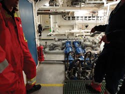
Correct configuration of a vessel’s auxiliary systems is essential to ensure the DP redundancy concept delivers the intended post-failure capability.
Independence
Independence of redundant equipment may be undermined by areas of commonality which introduce potential common cause failures. For example, the provision of automatic changeover between power supplies from different redundant groups may lead to independence being compromised if it allows critical equipment in different redundant groups to be supplied from the same distribution. A hidden failure in the changeover function may then impact the redundancy concept. If the presence of the changeover is not essential, then it may be safer to isolate the alternative supply at source to ensure that incorrect configuration cannot go unnoticed.
Where auxiliary systems have duty and standby pumps fitted for each redundant group, but each pump is supplied from a different redundant power distribution then the redundancy concept may become reliant upon the standby pump starting. Incorrect selection of the duty pump, combined with hidden failures in the standby pump, may affect the redundancy concept. The most robust configuration should ensure that the pump associated with the same redundant power group as the equipment served is always running.
Unavoidable areas of commonality are often present in fuel bunker tanks, seawater for cooling, and combustion air. Configuration errors can compromise the mitigations intended to address the risks of such commonality. Examples include the use of a single fuel purifier in simultaneous fuel transfer to day tanks in both redundant groups, the use of a single sea chest to supply a common seawater cooling manifold, and configuration of a single control air supply to keep ventilation dampers open for redundant machinery.
Autonomy
The ideal of autonomy in control systems for each redundant group is difficult to achieve. It is therefore common practice for single controllers to manage operation of all redundant equipment groups, with standby controllers ready to take over in the event of failure. Most redundant control systems will warn the operator if a configuration choice renders the standby controller unavailable, but configuration is still an important consideration.
For DP Class 3 vessels, the operator must often manually configure the alternative DP control station to ensure it is ready for a bump-less transfer of control. Where load-sharing of parallel generators is performed by a centralized controller, the architecture of the control system may reduce autonomy. In such cases, governor droop load-sharing mode may be the most robust configuration as it is independent of the centralized controller.
Effective decision support tools can prevent inadvertent configuration errors and deliver benefits to all stakeholders in DP operations.
Differentiation
Lack of differentiation may allow redundant equipment to be subject to failures from common external causes. Where a vessel design provides redundancy by duplication of equipment, but with each option using a common operating principle or common hardware or software, there may then be limited opportunity to retrospectively provide differentiation. However, in some applications it is required by rules and it is important that the chosen configuration reflects this.
DP position reference systems, for example, are recognized as being particularly vulnerable if differentiation is not provided. Classification societies require that at least two measurement principles be represented. This differentiation can be compromised by incorrect selection/configuration.
Correct configuration of a vessel’s auxiliary systems, power and propulsion plant, and associated control systems is essential to ensure the DP redundancy concept delivers the intended post-failure capability. The reality for many vessels, however, is that configuration is not managed effectively to support the redundancy concept, with bridge and engine room checklists only providing a record of configuration rather than providing direction or decision support. There is frequently a lack of understanding of how configuration errors may defeat the redundancy concept.
In recognition of the importance of DP system configuration, the IMO has taken an important step in the inclusion of a recommendation for the adoption of activity-specific operating guidelines (ASOG) as a decision support tool in the recent IMO MSC Circ 1580 ‘Guidelines for vessels and units with DP systems’. The concept of the critical activity mode (CAM), promoted by the Marine Technology Society (MTS) and International Marine Contractors Association (IMCA), is an essential part of the ASOG. CAM provides an agreed configuration table itemizing all essential configuration points that are necessary to provide the highest level of fault tolerance for critical aspects of anticipated DP operations.
In ASOG and CAM, vessel crews can adopt an effective decision support tool to prevent inadvertent configuration errors and deliver benefits to all stakeholders in incident-free DP operations. •
The author
Rupert Bambach provides dynamic positioning technical and operational consultancy for Noble Denton marine services as part of DNV GL - Oil & Gas. He has more than 15 years seagoing experience and has sailed as Master of offshore DP vessels, passenger ships, and yachts. He has a BEng in Electronic Engineering and MSc in Marine Technology and has provided services to shipowners, oil majors, and insurers for more than eight years.