Spar's novel riser support system solves workover motion problems
Thomas MillerCylinders cope with changing load conditions
Bardex Corporation
Victor E. Baugus
Oryx Energy Company
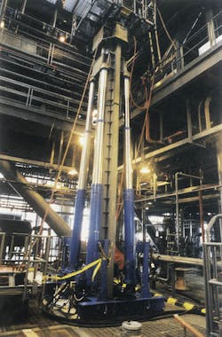
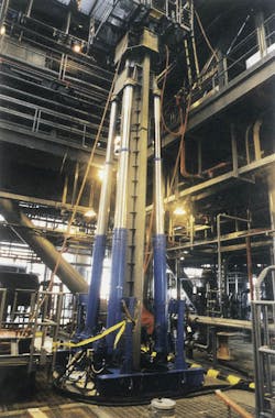
The Bardex adjustable riser support system was installed on the Oryx Energy Neptune Spar.The Oryx Neptune Spar, positioned in 1,930 ft water depths in Viosca Knoll Block 826 in the Gulf of Mexico, is a free-floating production-only vessel held on station by a six-leg taut catenary mooring system.
The spar is equipped with a unique adjustable riser support system (ARSS) that provides load support needed for the free-standing production riser string during workover/completion operations on the spar's 16 well slots. The system also resists vertical motion of the riser string due to environmental conditions when these operations are in progress.
Being a catenary moored structure, the spar is free to move to some extent in all six degrees of freedom. The wells are tied back to the surface trees by means of the 9 5/8 in. diameter, 53.5 pounds per linear ft production risers. The risers are located within a 32 ft by 32 ft center well area which passes vertically through the spar hull.
Each riser is individually supported by a buoyancy can assembly attached to the upper portion of the riser and carries the operational riser weight with a small margin of excess buoyancy. The riser/buoyancy can assemblies are designed to be self-supporting and are therefore not bolted or mechanically tied to the deck.
The buoyancy can assemblies are tethered to the bottom by the risers, and separate from the hull, generate some relative motion between the two. Normally, this relative motion is accommodated by the use of flexible pipe jumper lines from the well to the production manifold. This relative motion creates unique problems during well workover operations.
The conventional practice during well workover operations is to first place a blowout preventer (BOP) or sometimes a snubbing, coiled tubing, or wireline lubricator unit directly atop the well. The extra weight loads created by these additions (up to 45,000 lb in the case of the BOP) are transmitted to the well/riser string and must be supported in some fashion. Other concerns generated by the relative motion problem are flexing and fatigue of the BOP's elastomer seals, and positioning of down hole tools accurately within the well.
Finding the solution
The answer to these problems was to somehow secure the well riser to be worked on to the deck structure so that there was no relative movement between the riser and the deck. This would allow the deck to carry the extra loads, obviating the need for additional buoyancy. However, because of the unique features of the spar's riser system and hull, the riser being worked on could not simply be bolted to the deck. Further, to be most effective, the riser had to be secured at one of several elevations for long periods of time.For instance, during workover operations, the spar is positioned directly over the ocean bottom well location and the riser is supported so that it is essentially vertical. The production riser does not stretch very well, and with only a foot of weather-induced heave, the resultant load on the deck would increase by about 238,000 lb. In effect, having the riser bolted to the deck would convert the spar to a tension leg platfomm with the riser acting as the tether. During severe weather, the vessel offset and other motions could quickly build to a level sufficient to fail the deck structure or the riser.
Oryx Energy turned this challenge over to Bardex Corporation, the supplier of Neptune's linear chain jack mooring system. Bardex developed and executed the concept of a hydraulic adjustable height support structure that allows the riser to be raised or lowered in a fairly rapid manner to accommodate changes in load conditions. The use of hydraulics, rather than some means of mechanical lift, allows any overloads to be relieved by venting the hydraulic fluid.
System makeup
The adjustable riser support system consists of a base mounting structure with four 100,000 lb capacity telescoping hydraulic cylinders, a control panel assembly, a load monitoring system, and interconnecting hoses. A dedicated hydraulic power supply is used to power the ARSS.The system has a 12-ft stroke and holds the riser at its normal free floating height approximately 22 ft., 9 in. above the production deck, an elevation which corresponds to the normal workover/completion operational height. With the cylinders in the full retract position, the attachment point on the riser (the 28 in. OD stem that connects the riser and the buoyancy cans) is approximately 10 ft. 9 in. above the deck providing easier access for hookup. The actual riser length for all of Neptune's wells is adjusted in order to provide the same riser connection elevation.
The ARSS is capable of lifting the riser 6-12 in. above the riser's normal free floating height provided the resulting applied load does not exceed 400,000 lb. It is also capable of lowering the riser the full stroke length (12 ft, or any fraction thereof) below the normal free floating height without the application of hydraulic power.
As noted previously, in the event that a riser pulls taut as a result of unexpected environmental conditions, the ARSS is protected from overload by means of a hydraulic pressure relief system that allows the riser to pull the supporting cylinders in the downward direction once the load limit is reached.
Each of the four cylinders features special seals and valve components to ensure that there will be near zero leakage of the hydraulic fluid. The telescoping cylinders are hydraulically interconnected in pairs diagonally opposed. The ARSS may be operated with the cylinders controlled individually or in cross-connected (balanced) pairs. This ensures that there will always be at least two balanced cylinders providing load support should a malfunction of a hydraulic component occur, causing pressure loss in one or both of the other two cylinders. Operating in the cross-connected pair mode has the advantage of perfectly balancing the riser load between the cylinders.
With the cylinders in the extended position, the riser is locked off to the spar. As long as there is a load on the cylinders, they may be retracted without running the hydraulic power unit. The power unit is required when the load is removed in order to retract the cylinders.
In normal operation, the ARSS is left at the workover/completion height and the spar ballast system is used to accommodate the typical 11 in. variation in tides (which affect the loading seen by the ARSS).
Storm procedures
During a storm event, the pressure in the hydraulic system is monitored to verify that spar heave motions do not cause the load to exceed 375,000 lb. When that limit is approached, an alarm sounds, and the cylinders are manually retracted approximately 4 1/2 ft from the normal workover height in order to decrease the riser load on the ARSS.During a 100-year storm or hurricane (requiring evacuation of all personnel from the spar), the cylinders are fully retracted. This places load on structural members of the ARSS only.
Two things happen when stroking the cylinders all of the way down: first the load is transferred from being on hydraulics to structural hard points within the cylinders for more load carrying capability. Second the riser is "buckled" and "twisted" in the water below the keel which provides some slack to make it somewhat compliant when the high surge and wave activity hits the area where the spar is located.
AII ARSS system controls are located on the manifold attached to the ARSS frame. These controls include the directional control valves used to extend, hold or retract each cylinder; pressure gauges and relief valves; a balance line selector for connecting the diagonally opposed cylinders; and a relief valve selector for configuring the controls to limit cylinder pressure.
Camel through needle's eye
Because of the space confines on the Neptune Spar and the fact that the ARSS system is only needed for workover/completion activities, at the end of those activities it is de-commissioned and removed from the spar for storage on shore in an enclosed environment until workover activities recommence. This means that the ARSS system had to be compactly designed and capable of being broken down into sections small enough to pass through a four-foot square hatch opening leading to the production deck where it could be assembled (amongst the wells' flexible jumpers and stems) and moved to any well within the well bay for hookup to the riser.Bardex designed the mounting structure for the cylinders so that it can be separated into two frame weldments, each of which can be passed through the hatch using the platform crane. Once on the production deck, the two pieces are pinned together and anchored to the floor via swing-in dogs that engage slots on the floor beams.
Each of the cylinders is then passed down through the hatch opening for assembly on the mounting frame while it is still located directly underneath the hatch opening. Each cylinder pair is mated to a frame weldment section. The mounting structure is fabricated from standard wide flange shapes with steel skid pads (shoes) welded to the bottom flange. The skid pads are located at a spacing equal to the production deck beam spacing so loads are reacted directly to the principal members of the deck. The frame includes a post and saddle for each cylinder so that the latter can be secured during translation of the ARSS between well slots.
Other provisions
Special attention was given to protecting the ARSS system's hoses that connect the manifold on the control panel assembly and the four telescoping hydraulic cylinders. Because the system was to be positioned underneath the drill floor, Oryx was concerned that falling objects could sever the hoses, particularly at the time coiled tubing operations were underway.If a hose were to be severed, the hydraulic fluid in the ARSS system would be lost, one or more cylinders would retract causing the BOP to drop, and the coiled tubing could be parted, thus releasing the well fluids and creating the potential for a fire. To protect the hoses, Bardex encased them in armored sleeves and routed the lines so that they were close to or underneath structural members.
A problem that surfaced after the ARSS had been installed and operating for a period of time had to do with calcium chloride in the completion fluids. Again, because the ARSS is located underneath the drill floor, the completion fluids would spill down onto and eat into the hard chrome plated rods of the telescoping cylinders. The result was pitted rods that had to be resurfaced. Bardex had each of the reconditioned chrome plated rods encapsulated within a pleated Neoprene boot (Heeco Protecto Boot) which was impervious to the completion fluid. This solution has worked fine in protecting the rods. Fortunately, the rods are never exposed to the completion fluid for very long.
Authors
Thomas Miller, P.E. is Vice President, Engineering for Bardex Corporation in Goleta, Califomia, U.S.A.
Victor E. Baugus, P.E. was Neptune Project Engineer for Oryx Energy Company, repsonsible for the engineering of the entire spar in addition to this system.
Copyright 1999 Oil & Gas Journal. All Rights Reserved.

