Electrical grounding a key design consideration for subsea booster pumps and umbilicals
An effective system helps safeguard personnel, protect assets
Mike Zerkus, Ronnie Garza, Thierry Dequin,Genesis
The advent of subsea processing systems to enhance subsea well production and maximize total reservoir yield has introduced subsea booster pump systems to deeper water environments.
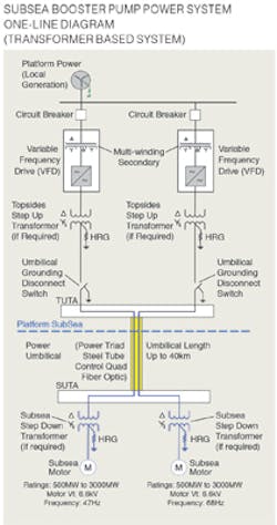
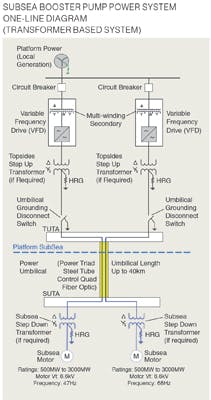
Subsea booster pump systems typically require the installation of medium voltage Variable Frequency Drive (VFD) systems on offshore platforms and use power umbilicals to transmit electrical power from the drive to large motors located on the seafloor. System design may call for two or more medium voltage three phase circuits to be housed within a common power umbilical. Alongside the power conductors are usually electrical quads, fiber-optic cables, and hydraulic and chemical metallic tubes.
Distances between the VFD drive system on the platform and the subsea pump motor may be 5 to 20 km (3 to 12 mi). Water depth for these installations range from shallow, or less than 1,000 ft of water, to ultra-deepwater that is 8,000 to 10,000 ft deep.
These subsea systems require material and component design suitable for highly corrosive sea water environments and high ambient pressures.
Maximum pressures are expected in motor penetrations and terminations due to proximity to pump process fluid. Maximum pressures in the subsea pump system are also exerted in pump and flowline and may be as high as 15,000 psi. Pump and motor seals along with barrier fluid systems segregate the pressurized process stream from the electrical termination points.
Reasons for grounding
Grounding of electrical systems serve several important functions.
Safety of Personnel. An effectively grounded system equalizes potential (voltage) of all bonded equipment, thereby reducing shock hazards. In a subsea system, grounding should help equalize voltage between connected equipment as well as between the subsea umbilical components.
Power system neutral stability. An effectively grounded system maintains neutral stability of a power system and enables the phase conductor voltage to be controlled within predictable limits, thus limiting potential power system over voltages. Grounding of the neutral securely anchors the neutral to earth/ground and thus helps to assure the suppression of transient line-to- ground over voltages. This minimizes damage to motor and power umbilical insulation and allows cable core design to a lower insulation level. Stable consistent voltage levels support the proper operation of equipment.
Fault current path. There are many different types of faults that could occur in a three-phase power system. A single phase to ground fault is the most common type of fault anticipated to occur in a subsea power system. A current flow path must be provided to enable detection of unwanted power system ground faults. Such detection may then, initiate operation of circuit protection to clear the fault.
Power umbilical EMI mitigation. Subsea booster pump power umbilicals generally have two or more power circuits, moving large currents at different frequencies. The very nature of a composite multifunction subsea power umbilical creates the possibility of electromagnetic interference (EMI). Proper shielding and grounding can limit EMI effects between components within an umbilical.
Insulation level. The level of insulation required for the power conductors is partially determined by the grounding scheme and the expected fault duration.
Design considerations
Systems design or materials specifications may be impacted by the grounding method to be employed. The key considerations are below.
Documentation. It is recommended to prepare a grounding coordination plan (grounding plan) to document subsea pump system ground requirements and decisions. Early during a project’s appraisal or select stage, grounding philosophies are helpful to communicate a vision for how a system under development may operate. Datasheets or drawings may be used as the project matures, and shared with all equipment manufacturers and engineering teams on the project. This will affect topsides, hull and subsea engineering teams.
Grounding disconnect switch. It is recommended to install a grounding disconnect switch upstream of the topsides umbilical termination assembly (TUTA) for all electric circuits in the subsea umbilical. Circuits in the umbilical are alongside each other in parallel for long distances. Energized circuits within the umbilical will induce electromagnetic force (EMF) on other circuits over the length of the umbilical. The induced EMF can manifest itself as a lethal voltage on the topsides electrical terminations, even on inactive circuits. A grounding disconnect switch will provide maintenance personnel with a safe method to eliminate the hazard and safely work on umbilical power or control circuits.
Umbilical static discharge. Another safety issue with umbilicals is static discharge. Due to the capacitive nature of long electrical cables, once power is removed a charge can remain on the electrical conductors for a long time. Also, all electrical components within the umbilical are subject to long time electrical static discharge, that can take a few hours generating a hazard to personnel.
Umbilical engineering. Although required in topsides electrical installations by applicable electrical codes, dedicated grounding conductors are not specifically required in subsea power umbilicals. The addition of a dedicated ground conductor to an umbilical is undesirable because it may add unnecessary weight, cost, and carries no current unless a problem occurs. An alternate approach is to omit the dedicated ground conductor and intentionally use the non-electrical metal components in the umbilical as the ground return path. This is referred to as the “structural ground path.” Extreme caution must be observed with the structural ground path approach. The metallic components and structural members of the umbilical design must carry the available ground fault current without overheating or destroying portions of the umbilical. The lack of a dedicated ground conductor requires careful analysis of the umbilical design. Alternatively, power core shield can be used as neutral, also called concentric neutral.
Analysis should include ground fault studies to determine available ground fault current from the topsides and subsea power system. Additionally, the umbilical design should be analyzed to determine the overall cross-sectional area of the ground path and how much fault current the ground path can carry. Power umbilicals are typically flooded and have the additional ground path presented by the sea water in the umbilical. Consideration must be given to the portion of the umbilical that is above the water line. This section will not have the advantage of the flooded section and may sustain damage if it cannot carry the available fault current without overheating.
EMI analysis. All of the electrical items are in close proximity within a composite power umbilical, which makes some EMI or cross talk inevitable. The principal EMI issue with subsea boosting pump umbilicals is inductive coupling between pump power conductors and steel tubes and control quads within the umbilical. Shields or screens around wire are very effective at reducing capacitively coupled noise but have little effect on induced EMI. Proper grounding can dissipate the induced voltages on the non-current carrying metal components of the umbilical. The physical arrangement of the umbilical cross section and functional components lay angles have a large impact on EMI performance. EMI/Crosstalk analysis of the umbilical is recommended to optimize the physical arrangement of components.
Cathodic protection. Stray currents within the umbilical can negatively affect cathodic protection system. Assessments should be performed to determine if induced voltages can affect the cathodic protection system and to determine if there will be any unexpected current flowing in the ground conductors.
Circuit protection. Circuit protection or protective relaying are directly affected by operating philosophy and ground system selection. The earlier a decision can be made regarding operation and grounding systems, the earlier protective relaying scheme can be chosen. Affected systems, components, or activities include:
• One-line drawing development
• Relay selection, relay configuration
• Current transformer size and placement
• VFD configuration and protection settings
• Subsea power umbilical circuit protection requirements
• Topsides and subsea transformers protection and specification (as required).
Coordination review. Medium voltage, low voltage and UPS supply systems should be reviewed to determine whether ground fault protection is coordinated with these supplies. Relay coordination inconsistencies could exist which may cause unexpected VFD operation in the event of a ground fault.
Insulation coordination. It is recommended that a document or data sheet be produced to track insulation requirements for each power system component. All components have the potential for being subjected to different voltage stress levels depending on the grounding system approach and operating philosophy employed. Available insulation materials compatible with seawater and ratings may become the deciding factor for transmission voltage for a subsea system.
Dynamic electrical effects. There are several dynamic electrical effects that can create large voltage and damage electrical insulation. These include transient voltages caused by the Ferranti Effect, reflected waves, and cable resonance. An analysis should be done to make sure the planned system (VFD, transformers (if used), umbilical, and motor) will cause or exacerbate these effects.
Codes and standards
Codes and standards required for proper grounding of offshore installations will differ depending on the location of the facility and authority having jurisdiction. Comparison of ANSI/ICEA/NEC North American electrical codes or IEC/CENELEC European codes considered for subsea system is provided as general illustration; however, code details need to be considered for design.
Conclusion
It is recommended that pump drive systems be designed to operate with fault, but in actual practice operate with the philosophy to immediately clear faults. This allows operators to inspect fault conditions and make an informed decision regarding continued operation of the subsea booster pump with a fault in place. It is important that project team representatives from operations, production controls, subsea pump controls, and subsea power discuss and reach agreement on this as it will impact every disciplines design.
Understanding and properly addressing electrical grounding considerations for subsea booster pumps system is essential for the design of an effective grounding system that will safeguard personnel, protect valuable installed assets while optimize procurement and operation cost of the system. •