First riser-deployed ESP in the GoM
David Cocciolone, Anadarko Petroleum
Tiffany Pitts, Mark Ohl, Peter Lawson - Baker Hughes Centrilift
After producing 1.7 MMbbl of oil, pressure depletion at the East Breaks 690 No.1 dictated the need for artificial lift to capture substantial remaining reserves. Various artificial lift technologies to overcome slugging and liquid load at a water cut of just 5-10% in the 6-in. (15-cm) riser and subsea flow line were studied. Ultimately, Anadarko Petroleum settled on an electrical submersible pumping (ESP) system. The ESP was installed in February 2007, providing dramatically higher flow rates and an increase in ultimate reserve recovery of 35%.
Gas lift and Centrilift’s patented ESP system riser technology were analyzed. Subsea wells present technical challenges for traditional gas lift systems. The tieback distance from the production platform is an issue for gas lift boosting capabilities as is declining bottomhole pressures in maturing wells.
The ESP riser lift system mitigates slugging, prevents load up, produces at higher rates, and increases ultimate recovery. By boosting pressure at the base of the riser, an ESP prevents slugging from occurring in the riser and increases production. A lower abandonment pressure is possible with ESP technology, resulting in additional recoverable reserves from the well. ESP systems do require more detailed planning. Issues such as high gas fraction, power supply from the spar and the fabrication of a wellhead adapter to hang the tubing and ESP from the riser tieback required consideration. However, the potential for sizable production gains as well as additional recoverable reserves outweighed technical issues.
ESP system modeling challenges
The East Breaks 690 No. 1 well, in 4,200 ft (1,280 m) of water, is a 4.5-mi (7-km) subsea tieback to the Anadarko operatedNansen spar in the Gulf of Mexico. The spar consists of nine dry tree wells and six subsea wells. Some of the subsea wells have been producing for over five years, and pressure depletion and increasing water production have reduced production volumes. Therefore, developing engineering solutions to prolong the life of these subsea tiebacks was increasingly important.
Application engineers required as much well information and production characteristic data as possible to design the most effective ESP system. This data was input into a proprietary ESP sizing and simulation program. Based on this production data, the program generated an ESP system design and a unique performance curve for the system. However, unknown or variable factors at EB 690 No. 1 made ESP system modeling more complex. The impact of hydrate plugging in the flowlines on the pump intake was a major concern, but it was difficult to quantify the amount of blockage. Another major design issue was to find the ideal point at which Anadarko production increase targets could be achieved without gas locking the ESP.
Final design
The EB 690 No. 1 was still a flowing well and capable of higher rates if further drawdown was achievable. By varying the frequency of the ESP, the pump intake pressure can be reduced to increase production rates, but this correspondingly increases the percentage of free gas in the pump intake. The application engineers evaluated several ESP models before settling on a design based on a pump intake pressure of 1,200 psi (8.3 MPa) at the pump setting depth of 3,200 ft (975 m). The pressure at the pump was calculated as the best match based on well production history and modeling by Anadarko.
The final ESP system design included a 116-hp motor with a tandem six-chamber seal; a high-volume vortex gas separator; an 89-stage abrasion-resistant pump; Monel armored cable; a downhole sensor, and a variable-speed drive. Due to high intervention costs for system change outs, run life is a major concern with any offshore ESP installation, so longevity was a major system design criteria for EB 690 No. 1.
The abrasion-resistant pump design improves ESP run time through a variety of features, including radial support, abrasion resistant characteristics, and added thrust support. The mixed flow stages used at EB 690 No. 1 are specifically designed for high flow rates.
High gas fraction
Recognizing that the high gas fraction at the riser base was a serious issue, the gas separator was a critical part of the system design. At 1,000 cf/STB and a gas fraction at the pump intake of 46%, this was on the high side of what the pump can handle at the design intake pressures.
With the ESP run on tubing inside the existing production path (the 6-in. [15-cm] riser), gas could be separated prior to entering the pump and produced up the riser annulus. The liquids would be sent through the pump, up the tubing, and into the existing production manifold.
With downhole separation sending gas to the annulus, the ESP system was constructed of stainless steel or equivalent. Though the gas only had a CO2 concentration of 0.2 mole percent, the possibility of 4 MMcf/d of gas traveling up the backside meant that any equipment run in the riser would need to be CO2 corrosion resistant. The body of the riser consisted of 304L stainless steel, so material compatibility was an issue. The integrity of the ESP cable was of particular concern, so Monel armored cable was chosen to maximize the life of the cable and ensure material compatibility. A lead barrier was also used to prevent any gas from migrating into the line from the annulus.
Downhole monitoring
Downhole monitoring was necessary due to high production rates and previous flowline high pressure drops caused by the onset of hydrates. A downhole sensor was included to monitor downhole pressure, temperature, and motor temperature. The ability to monitor the pressure drop between the subsea wellhead and the pump intake (near the base of the riser) helps monitor pipeline performance over the life of the well. At the first signs of abnormal pipeline pressure drop, action can be taken.
The variable speed drive (VSD) was critical to the overall ESP system, providing both a link to the downhole sensor and a means of system control. Modeling the well network in current conditions was challenging, and it was apparent the well would need multiple adjustments to optimize flow upon startup.
Due to the 5-mi (8-km) long flowline, history of gas slugging, and declining bottomhole pressure, the VSD was necessary for control at both start up and throughout the life of the system as well conditions change. Although the spar has limited deck space, a secure location was found to place the drive, transformers, annulus manifold, and wellhead.
Workover operation
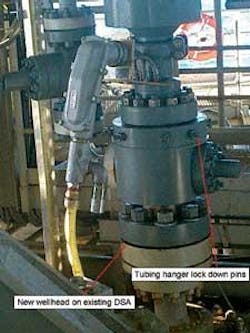
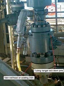
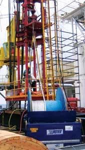
A hydraulic workover rig was chosen as the method of installation, as it was quickly mobilized at low cost and provided the recommended run in rate of 1,200 ft/hr (366 m/hr). Furthermore, with no pressure control needed, the BOPs were eliminated, saving on costs and rig-up time. After the flowline was displaced with fluid, the flowline valves above the riser tieback were nippled down and the wellhead was mated to the existing double studded adapter. This is where the tubing hanger would be landed and cable penetrations made.
With no pressure control required, the ESP and tubing were run without any riser above the wellhead. A bell nipple was manufactured to allow for the diversion of fluid to a tank should any be displaced out of the flowline riser when running the ESP in the hole. The ESP assembly was essentially guided into the bell nipple above the wellhead.
It took about 24 hours to run 3,124 ft (956 m) of tubing and downhole components with cable and clamps. With the desire to flow fluid up the annulus, no downhole packer was set now was the assembly rigidly connected to the riser downhole. All the weight of the tubing and pump components were distributed at the wellhead.
Well startup
After the well was started, it was observed that when running the pump at a target frequency, the downhole current would fluctuate significantly from full load (35 amps) to underload conditions. These underload conditions indicated gas slugs moving through the pump, causing it to run nearly in idle. To alleviate this, the pump was programmed to speed up when gas enters the pump (low current conditions).
The increased frequency allows the pump to do more work, avoiding extreme underload conditions. A high current limit was programmed in as well. When fluid hits the pump and the load increases to near 35 amps, frequency automatically adjusts down until the maximum current remains at 35 amps, preventing overload. The frequency never adjusted lower than 54 Hz – still sufficient speed to move fluid through the pump.
After this adjustment was made, the EB 690#1 was tested by sending both the tubing and annulus to the test separator. A 12-hour well test resulted in production of 3,931 b/d of oil and 3.9 MMcf/d of gas versus pre-ESP average production rates of 1,400 b/d of oil and 1.4 MMcf/d of gas. Liquid dumping from the separator was fairly constant and slugging was not a serious problem.
One question remaining was the ratio of production between the tubing (pump) and annulus. Therefore, the tubing was sent to the test separator and the annulus was sent to the IP separator, with both vessels being at nearly the same pressure. This would show not only rates from both sides, but also how much gas was being diverted to the annulus – basically how effective the gas separator was performing. Results of the test were as follows:
- Oil production through pump – 2,142 b/d
- Gas production through pump – 1.8 MMcf/d
- Oil production through annulus – 1785 bbl/d
- Gas production through annulus – 2.1 MMcf/d
As shown, about 55% of oil production is produced through the pump, along with about 45% of the gas production. Surprisingly, a sizable amount of the fluids production is producing up the backside.
Pressure effects
ESP intake pressure at the base of the riser held fairly steady at just under 800 psi (5.5 MPa), whereas unboosted pressure at this depth was 1,500 psi (10.3 MPa). This corresponds to a lower flowing tubing pressure. The pressure drop is transferred all the way to the perforations, and has greatly increased reservoir drawdown to the point where the well is slightly choked back as to not exceed reservoir voidage guidelines.
With lower bottomhole pressure, EB 690 No. 1 is expected to continue producing at higher rates, resulting in higher drawdown and the mitigation of severe slugging. By boosting the riser, Anadarko anticipates the abandonment pressure of the well will be lowered by 500 psi (3.4 MPa). Looking at historical well production, a 500-psi abandonment pressure drop will increase estimated ultimate recovery of this well by an estimated 35%.
Installation of this riser lift system tied into the flowline of the EB 690 No. 1 well resulted in immediate benefits. Production increased by 2,900 b/d of oil ($145,000 per day at $50/bbl), slugging was reduced and liquid loading ceased. Estimated ultimate recovery from the well is expected to increase by 35% with the lowering of the abandonment pressure. Overall, the economics of the project are excellent with finding and development costs for the project under $4/boe and payback on the entire ESP system and engineering services in nine days with an annualized ROI of 4,300%.


