Wet insulation evolves to meet subsea flowline performance demands
Rob Hunter - 3M Oil and Gas Business
Wet insulation pipe use supplanted pipe-in-pipe insulation as the most used way to meet flowline performance demands over the past five years. Glass microsphere technology has fostered development of flowline insulation alternatives that reduce thermal conductivity and make deepwater hydrocarbon recovery feasible.
Expanding deepwater E&P in recent years has prompted major technology investments in flowline design to control thermal losses in long subsea tiebacks and in wet tree completions.

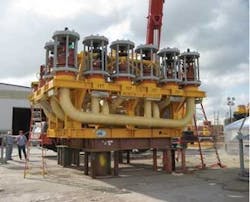
There are subsea assets where it is economically viable to expand peripherally to recover additional reserves at reach-out distances of 50 km (31 mi) or more. Extended subsea pipe lengths and a trend to deeper and hotter drilling conditions have prompted a search for flowline insulation technologies with increased mechanical strength and reduced heat transfer.
A range of insulation approaches has been developed for varying subsea conditions, and these designs often use glass microspheres in syntactic foam insulation for demanding depth and pressure conditions.
Adam Jackson, Ph.D., is manager, Global Flow Assurance Technologies for Bredero Shaw in Trondheim, Norway. This Canada-based firm provides corrosion protection, thermal insulation and coating services to offshore and onshore oil and gas industries. “In the early years of deep water operations, pipe insulation was something of a black art and very little data was available on insulation performance,” Jackson recalls. “Insulation system design has become much more robust in recent years, with a range of material alternatives. Models are well refined today, and investments in flowline insulation can be made with a high degree of certainty in the results.
“Insulation demands are increasing as subsea oil production moves to deeper and ever more demanding locations,” Jackson continued. “Thermal loss requirements are calculated in terms of U-value and expressed as Watts/sq m Kelvin (W/m2K). The heat transfer coefficient required for a particular application is based on multiple inter-related factors that include water temperature, well output temperature, flow rate, and flowline length and diameter. An insulated flowline that meets the target U-value for a given location and operating scenario will limit heat loss of transferred fluids to an acceptable temperature differential from the seabed to the surface.
In 3M’s experience, wet insulated syntactic flowline U-value performance as low as 2W/m2K is feasible.
Flowline insulation alternatives
There are three approaches to insulated flowline for deepwater operations: Pipe-in-pipe (inner and outer steel pipes with an insulating material in the annular space), wet insulated flowlines (steel pipe with a surrounding layer of exposed composite insulation), and insulated flexible flowlines (a composite structure with a core of helically wound steel and extruded plastic layers and insulation added in the form of flexible wrapped syntactic insulation).
1. Pipe-in-pipe
Insulation in pipe-in-pipe construction is isolated from physical damage during handling and placement, so a relatively low strength material with high insulating value can be used. Pipe-in-pipe insulated flowline is heavier than wet pipe insulation, so its use may depend on the availability of required installation equipment. Construction and placement costs for pipe-in-pipe flowline generally exceed those of wet insulated flowline. Low U-values and high insulation performance can be achieved with pipe-in-pipe insulation, but its cool down time may be shorter than that of wet pipe insulated flowline.
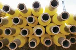
2. Wet insulated pipe
Direct insulated, or wet insulated, pipe now is the most commonly used flow assurance alternative for deepwater flowlines. Wet insulated flowline is produced by several manufacturers. In this application, steel pipes are direct coated with a syntactic foam material and placed on the seabed generally without external protection or cover. Low-density hollow microspheres in this syntactic foam composite reduce both the weight and thermal conductivity of the pipe coating.
3. Flexible insulated pipe
Technip is an engineering and construction services company and a supplier of flexible risers and flowlines. Technip USA Lead Flexible Pipe Specialist Julie Ingram says flexible pipe insulation takes the form of wrapped syntactic tape layers.
“This tape material is an extruded polypropylene thermoplastic mixed with hollow glass microspheres,” she says. “Sphere content is generally around 45% by volume, yielding a tape density of approximately 0.7 g/cc (0.025 lb/in3), and this syntactic tape insulation is suitable to depths of 3,000 m (9,842 ft). Technip has flexible pipe insulation materials with even lower thermal conductivity, but with reduced water depth capacity.”
Flexible flowlines can be cost effective as the higher cost for the more complex pipe composition is compensated by simpler installation and more direct flowline routing made possible by its flexibility. Flexible flowlines offer installation efficiencies because extended segment lengths are possible, and reeling and installation operations are simpler than handling rigid pipe.
According to Ingram, flexible risers have been one of the enabling technologies for FPSOs and still are selected as risers for more than 90% of them. In addition, flexible pipe can have a lower hang-off angle for a more compact seabed footprint, which is desirable in crowded field arrangements. Flexible pipe also can be recovered for reuse or decommissioning.
Syntactic foam insulation
Jerry Franklin, technical project manager for Dow Hyperlast, part of Dow Polyurethanes, a business group of the Dow Chemical Co. and its subsidiaries, Derbyshire, UK, explains that syntactic foam pipe insulation has been used in oil recovery operations since about 1986.
“The first syntactic foams were made with polymer or plastic beads, which are inexpensive and easy to handle,” he says. “The beads displace resin in the matrix, reducing its weight and density and adding insulation value per unit of thickness. However, plastic beads are structurally weak, limiting the depth at which this type of syntactic foam wet insulation can be used to approximately 250 m (820 ft), although a higher modulus version is available which extends capability to 600 m (1,968 ft).
“Microspheres comprise nearly 50% of the volume in a syntactic foam,” he said, “and this component improves insulation value by approximately 20%. Thus for a given U-value, the insulated pipe diameter can be 20% less with a syntactic foam than with resin only.”
Franklin notes that by the mid-1990s the depth of subsea oil exploration had increased substantially, and interest began to develop in glass microspheres for syntactic foam wet insulation because of its higher compressive strength.
“One of the first major installations of glass microsphere syntactic wet flowline insulation was for the La Ceiba field in Equatorial Guinea in 2001,” Franklin recalls. “This material quickly became a standard component for deep and very deepwater flowline insulation applications. That same year, a large project in the Gulf of Mexico required thousands of tons of wet syntactic foam insulation material comprised of polyurethane and more than 900 tons (816 mt) of glass microspheres.”
Syntactic foam composition
There are three primary categories of wet flowline insulation construction, polyurethane, polypropylene, or epoxy resins. The first two are relatively flexible elastomers, while epoxy is less flexible. Flexibility of wet pipe insulation can be an asset in pipe handling while more rigid insulation may offer increased compressive strength.
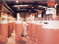
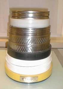
Photo courtesy of Bredero Shaw.
With less flexible epoxy wet pipe insulation, the resin structure can have greater hydrostatic pressure capacity than the microspheres in the matrix. Therefore, the ultimate pressure and depth capacity of the insulation is less constrained by the isostatic pressure rating of the microspheres. In less rigid polyurethane and polypropylene insulation materials, hydrostatic pressure is transferred to the glass microspheres in the matrix. Therefore, the compressive strength of the glass bubbles determines the pressure resistance and ultimate depth capacity of the insulation.
Franklin explains that each syntactic foam has distinct processing and performance advantages and is suited to particular application.
Polyurethane insulation has the advantages of flexibility, mixing ease, and simple syntactic formulation. Polypropylene exhibits increased hydrolysis resistance and a high temperature rating. Epoxy insulation has a higher modulus and excellent hydrostatic load resistance compared to the other two materials.
Wet pipe construction
Jackson explains that polyurethane and polypropylene wet insulation materials are applied commonly in a factory setting to pipe lengths of approximately 12 m (39 ft), with cutbacks for girth weld joints. Pipes segments can be welded during placement operations at sea, or joined onshore and reeled for barge transport and placement. Joints generally are coated with specialized polyurethane or polypropylene systems prior to reeling onshore or during J-lay at sea.
Epoxy wet pipe insulation typically is cast on pipe segments up to about 25 m (82 ft) long. Coated pipe ends may be welded or joined with couplings, and fitted with an insulating field joint such as molded half-shells or an epoxy or polyurethane coating as they are placed.
Jackson estimates that polypropylene is used in about 65% of wet insulated flowlines installed worldwide, with polyurethane accounting for 30%, and epoxy for the remaining 5%.
Socotherm Group develops wet pipe insulation, particularly syntactic polypropylene. “We developed our first polypropylene wet pipe insulation in 1998, and soon after began to explore syntactic formulations to reduce density and increase insulation performance per unit thickness,” Socotherm project manager Marcos Mockel of Buenos Aires, Argentina, explains.
“Today, Socotherm has a range of proprietary syntactic polypropylene insulation products, each of which contains 3M glass microspheres,” he said. “We’re presently working on products for ultra deepwater applications in excess of 2,500 m (8,202 ft).”
According to Socotherm Technical Manager Giovanni Portesan, the conventional 1.5X depth safety factor for subsea systems requires glass bubbles with 450 bar (45 MPa) hydrostatic capacity at 3,000 m (9,842 ft), giving the necessary margin of safety above the actual 300 bar (30 MPa) performance required for that depth.
“This safety margin has to do with pipe laying operations as well as performance at depth,” Portesan says. “Producers cannot risk damage to insulation because of the extreme cost and complexity of replacement.”
He says that the longest installed wet insulated flowline by Socotherm is approximately 40 km (25 mi) long – an extended distance made possible by a unique combination of high incoming temperature and a relatively low wax appearance temperature requirement for that particular project. In general, the firm’s syntactic polypropylene insulated flowlines range in length from 10 km to 25 km (6 mi to 15.5 mi).
Cuming Corp. of Avon, Massachusetts, was also an early adapter of glass microspheres for undersea applications, beginning with components for deep-sea exploration. Lou Watkins, vice president and chief technical officer, says Cuming supplied its first glass syntactic wet flowline insulation in 1995 in response to increasing water depth and insulation requirements.
“It was not until 1995 that the depth and temperature requirements of offshore oil wells increased to the point where the economics of syntactic foam made sense,” Watkins says. “Cuming began receiving orders about that time for insulation for both flowlines and subsea equipment in the Gulf of Mexico, and was a pioneer in this new technology. The company specialized in epoxy-based syntactic foam materials, using 3M glass microspheres.”
According to Watkins, Cuming’s first wet pipe insulation products were intended for use down to 1,000 m (3,281 ft), while current materials are suitable for use at 2,000 m (6,562 ft), and a third-generation insulation under development will be rated for 3,000 m (9,842 ft).
“The challenge for new insulation products is to create cost-effective composite materials that can survive ever-increasing heat and pressure,” Watkins says. “The secondary concerns are processing and application. It is often necessary to apply insulation materials to pipe and equipment in the field, such as in a shipyard or a fabrication plant, and materials must be forgiving and easy to use.
“The 3M glass microspheres are the hollow displacement fillers of choice for syntactic foam because they offer excellent strength, low density, and uniform properties,” Watkins says. “They are, in effect, ‘precision packaged air’.”
He estimates that just five years ago pipe-in-pipe insulation accounted for 90% of subsea insulated flowlines. Flexible pipe and wet insulation accounted for the balance. Today the formula is reversed, with an estimated 90% of installed flowlines consisting of wet insulated pipe. “Glass microspheres have made expansion of the offshore industry possible drilling as well as production.”
Mockel of Socotherm concludes, “Specifying wet pipe insulation is not a simple process because each field setting and well operation has its own construction demands. We find that wet insulated flowline is the system of choice for the vast majority of projects because of its installation efficiency and effectiveness, but the final decision is always determined by field infrastructure, line length, U-value requirements, and the overall design structure of the field, and not by depth alone.”
3M Glass Bubbles are unicellular microspheres made of soda-lime borosilicate glass with a high strength to density ratio. These glass bubbles are engineered to be low density fillers in the range of 0.12 – 0.60 g/cc (0.004 – 0.022 lb/in3). They are chemically inert and have high water, pressure, and temperature resistance.
Since they are perfectly spherical, 3M glass bubbles have a much lower surface area to volume ratio than other fillers. This allows for higher volume loading in a base resin system. The 3M glass bubbles have an average particle diameter of 30 to 60 μ, and by nature do not tend to segregate by size but remain evenly distributed in transportation and storage, and stable during the manufacture of syntactic foam composite.
Glass bubbles are used in drillstring riser buoyancy modules and to make low density casing cement slurries. Recent tests in well drilling and completion fluid applications were positive and indicate a potential for maintaining under-balance during perforation.