Flowline design enables deepwater production offshore Africa

Curt Giambattista
Antonello delle Canne
Stephane Couprie
Jacques Vila
Saipem
Hervé Guéveneux
Christophe Vuattier
Total Upstream Nigeria Ltd
In June 2009, Saipem SA successfully completed the subsea installation of the flowlines at the AKPO project in deepwater offshore Nigeria as part of the EPCI contract with Total. The in-field flowlines consisted of 21 mi (34 km) of 10-in. production lines and 23 mi (37 km) of 8- to 10-in. injection lines.
Challenges faced during detailed engineering included design of the flowlines and spools to accommodate large expansions induced by high temperatures, the susceptibility of the lines to lateral displacements and pipe walking, and the necessity for project execution in parallel with qualification for the thick thermal insulation materials and application procedures.
AKPO, in OML 130, produces condensate for offshore loading to tankers and exports gas by pipeline to the onshore Bonny LNG plant.
Total is operator with 24% interest; partners are Petrobras, Sapetro, CNOOC, and Nigeria's NNPC.
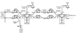
AKPO has a large spread moored FPSO connected to subsea production equipment (44 wells). The flowlines and risers system consist of four production loops (10 in. ID) connected to the FPSO via steel catenary risers, four water injection lines (10 in. ID), one 8-in. gas injection line and one 16-in. gas export line.
Flowlines directly connected to the risers were connected at the flowline termination (FLET) to an anchor pile to restrain movement toward the FPSO. The connection is a chain and chain-stopper system.
The main constraint that drove design of the flowlines and the configurations of spools and jumper terminations was the thermal requirements. Additionally for all subsea lines, the strength criteria and the interfaces and installation requirements were the constraints.
Saipem designed the insulation of the production loops (flowlines, SCRs, and connecting FLETs, spools and jumpers) to comply with project overall heat transfer coefficient (OHTC or U-value) and cool down time (CDT) requirements.
This was achieved by using multi-layer polypropylene for the flowlines, SCRs, spools and jumpers (straight parts), and polyurethane for the piping incorporated in the FLETs and spool/jumper bends and field joints.
The mechanical flowlines design, including FLETs, spools (connecting the FLETs to the manifolds or other FLETs), and jumpers (connecting the trees to the manifolds or to the FLETs/ITAs), was driven by the following:
Flowlines. The maximum design temperature exceeded 100°C (212ºF) for the production flowlines. The susceptibility of flowlines to pipe walking was to be studied with an eye on transient temperature profiles and the number of prescribed startup/shutdown cycles. Finite element (FE) analyses assessed pipe walking and considered the pipe/soil resistance. The interaction between lateral buckling and walking was mitigated to prevent damage of the spools.
Spools and jumpers. Spools and jumpers were supported by seabed and low points had to be minimized. Horizontal connectors were prescribed and the design had to comply with a new concept of horizontal connector. The linepipe section of the production spools was very stiff (D/t ratio in the order of 10). Design of the spools had to comply with installation spread requirements.
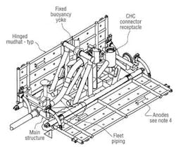
Subsea structures. The subsea structures have integrated mudmats with foundations designed to slide on the seabed. The FLET foundation was studied for static loading and cyclic displacement under startup and shutdown cycles.
Design execution
The thermal design resulted in insulation thickness for the five-layer polypropylene coated pipes of 104 mm for the flowlines and 100 mm for the SCRs. The FLET piping was insulated with solid polyurethane in a thickness of 80-160 mm.
Spools and jumpers were insulated with a combination of five-layer polypropylene for straight sections and solid polyurethane for bends and field joints, with coating thickness ranging from 80 mm (jumpers) to 104 mm (spools).
In general, the calculated achieved thermal performances were an OHTC of 2.9 W/m2 and a CDT of 15 hr. The design used both FE analysis (COSMOS) and computational fluid dynamics (FLUENT).
Insulation of the anchoring between the piping and the FLETs was a special case, due to the complex geometry of the connection that required the insulation of the structural bracings.
The braces were filled with mineral wool to prevent air convection. As part of the commissioning phase, a performance test consisting of running both stationary fluid conditions and transitory conditions on the full production loop was done to prove thermal requirements were met.
The displacements of the flowlines sections directly connected to SCRs were analyzed using the DEEPLINES FE software, taking into account the static and dynamic behavior of the adjacent SCR. The results of the thermal expansion analyses showed a maximum expansion value at the production flowline end of approximately 2 m (6.5 ft). The AKPO production flowlines sections are short, and the buildup of axial compressive forces due to thermal expansion would have resulted in pipe walking. Lateral buckling was not found to be a major concern on these flowline sections.
All the lines not directly connected to the risers show susceptibility to pipe walking, and the resulting ratcheting of the end expansions was taken into account. In the worst case, a 3.3 m (11 ft) contribution to end expansions was calculated.
The resulting total maximum displacement at the termination FLETs, considering both thermal expansion and walking effect, was too large to be accommodated by the relevant spool. The maximum displacement value found overall was about 4.5 m (14.75 ft).
To prevent the production lines from walking, skirted anchors mounted on a flowline quad joint were designed to be installed in the middle of the line sections, not connected directly to the riser. This structure is connected with an anchor clamp, which also required insulation.
The advantages of this solution are simple design, easy fabrication, and the fact that the anchor is laid together with the quad joint to which it is connected and does not require separate installation. Ten mid-line skirted anchor structures were installed.
The water injection flowlines were found to be sensitive to lateral buckling. To mitigate the impact of lateral buckling, water injection lines were laid partially flooded.
Flooding has two main effects:
- Increased weight during installation, which caused increased pipe embedment and so increased axial soil resistance. This contributed to a reduction in thermal end expansions.
- The end cap effect, created by the water head inside the flowline during laying, also increased the residual tension on the as-laid flowline to further reduce thermal expansion and compressive buckling load.
Fatigue analyses showed that, in the worst case, a 29% fatigue damage would have accumulated. The allowable is 33% based on DNV OS-F101. The S-N Curve used for the fatigue analysis of the flowline welds was the DNV Class F1 S-N Curve.
Water injection lines were sufficiently long to prevent walking.
Walking versus lateral buckling also was studied for a 12-km (7.5-mi) flowline section not directly connected to the SCR. The FE analysis showed that due to the slope effect, a buckle generated in the first 2 km (1.25 mi) of the flowline section could de-couple the line in two sections (respectively, 10 km and 2 km long) at the buckle location. The short section also was installed on slightly sloping soil; both the thermal and the slope effect contributed to the walking of the flowline toward the buckle. The analyses showed that a marginal but negligible tendency to walk could not be excluded.
Based on these results, it was decided that no walking mitigation measures were needed. As a contingency, a grab point was installed on the water injection FLET potentially subject to walking. If long-term observations show unexpected walking of the FLET, this tendency can be stopped by connecting the grab point to a post installed anchor.
The same analyses were performed on the gas injection line. With less demanding design conditions, these lines were verified without the need for special mitigation.
The main challenge for the production spool and jumpers design was to identify a shape flexible enough to accommodate the high loads due to FLET displacement, measurement tolerances, fabrication tolerances, and structures settlement ranging from 200 mm to 400 mm.
There were a number of items of particular concern. High stiffness of the production spools section (having a D/t ratio in the order of 10) was a challenge; and material strength de-rating factors, due to high temperature, had to be considered in operating conditions. For Duplex jumpers, using an allowable stress design (ASD) approach, thick pipe sections would have been required to accommodate the load effects generated by the large fit-up tolerances. This would have increased the rigidity of the spools and consequently the interface loads.
A strain-based approach was developed to verify the bends. FE analyses were performed that considered the non-linearity of the material. The optimized configuration was defined for a maximum allowed principal strain of 0.3%. To use the same configuration and an ASD would result in stresses well beyond the allowable limits.
Further, a statistical approach was developed to reduce conservatism in the assessment of loads due to fabrication/metrology tolerances. The fit tolerances due to metrology (+/-1°), spool fabrication (+/-0.5°), and hub-receptacle misalignment (+/-2.2°) that the deterministic approach defined as on the order of +/-3.7° were reduced by approximately 20% to +/-2.9°.
To reduce the impact of dimensional control, special tools/procedures were developed, including a way to implement the accuracy of readings during the metrology survey of the connector on the seabed. For onshore fabrication, ways were developed to reduce the fabrication tolerances relevant to subsea connection elements mounted on the FLETs and ITAs, and to reduce the angular fabrication tolerances at the connection location for spools and jumpers.
The final shape of the production loops included side loops at both ends that increase the flexibility of the suspended spool sections to reduce loads at connectors. By using side loops, the bending loads due to reactions transmitted by the soil are also partially transformed in torsional loads.
The main design problem for the injection jumpers was that the shape resulting from a conventional design approach was very complex. Design by analysis (DBA) procedures and reliability methods resulted in optimized and more compact spools with eight bends, compared to the 16 that would have been required for the same spool designed using ASD.
Following definition of the maximum displacement range for the subsea structures, dedicated FEA were performed to identify the maximum stresses variation on the soil due to cyclic loads and maximum FLET settlement, including primary consolidation of the soil below the FLET, contribution of soil scraping and cyclic loading of the soil.
Qualification activities
An important technological challenge at AKPO was the use of thick wet insulation for the production SCRs and flowlines (including spool and jumpers). More than 50 km (31 mi) of pipe, including 15 km (9.3 mi) of riser pipe, was coated with thick multi-layer polypropylene (5LPP) in a Nigerian coating plant. The insulation layer of the 5LPP coating was made of syntactic polypropylene. There also were more than a thousand field joints performed onshore for the production spools and jumpers.
The selected coating thickness was 104 mm, for an overall outer diameter of 511 mm (20 in.) to satisfy thermal performances requirements for stationary and transient conditions. The selected field joint insulation system was solid polyurethane (PU) applied offshore during both the quad joint fabrication (horizontal casting in the J-lay vessel firing line) and in the final line assembly (vertical casting in the J-lay tower). The overall scope included more than 2000 PU field joints to be prepared offshore.
An extensive project-specific qualification campaign was carried out for the overall SCR and flowline system, including 5LPP coating and PU field joint system. The qualification scope focused both on material testing (performed on small-scale samples machined from full-scale applied coating) and on integrity of the complete system. A material testing campaign confirmed material properties through short-term testing of representative samples, supplemented by long-term testing (3,000 hr.) to verify aging properties of materials in project conditions.
Full-scale testing included bending (up to 0.5% of steel skin strain), fatigue cyclic bending (up to 1 million cycles), thermal tests and simulated service tests.
All full-scale tests included the insulated field joint because this is often the most critical part of an insulation system. Special attention was paid to the PU/PP interface adhesion. An adequate PP chamfer surface preparation and activation was defined to resist a combination of loads, ranging from initial stress induced by PU shrinkage during curing, the bending strain (for SCRs and spools), and thermal contractions due to cold seawater.
The overall testing qualified the insulation and field joint design, the application procedure and the equipment setup, and confirmed the Inspection and Test Plan (ITP).
A critical challenge of such a large number of thick offshore field joints is robust in-country application procedure, i.e. systematic, repetitive, and reliable. Achieving this required an investment in equipment and training. Integrating a long qualification process required the purchase of the main coating line and field joint process early in the project and performing some early pipe coating in Nigeria well in advance of the delivery of the project pipe. All long-term tests were done on those early coated pipes; final pre-production testing was done on actual project pipe before installation.
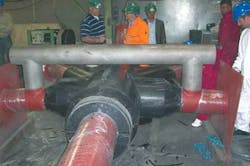
FLET anchor insulation

The FLET anchor insulation required solid PU on structural bracings welded to the FLET anchor sleeve. This insulation was validated on a dedicated mock-up to confirm the mold and casting process. After confirming the casting process, the insulated mock-up was used for global thermal assessment by infra-red camera to confirm the absence of cold spots.
The mid-line skirted anchor was designed to transfer the anchoring axial load through the thick PU/5LPP insulation. A different load resistance was required during installation and field application. Load was transferred through the contact between a steel ring and the edges of a PU recess. The 5LPP coating was machined to mid-thickness at the location of this specific PU casting.
The coating stress and contact loads first were evaluated by FEA and simplified material behavior representation. This showed some localized high stress areas that were judged significant for the PU material, so full-scale test of this load transfer mechanism were done. Tests confirmed that the PU casting could resist more than three times the project requirement signs of cracks or permanent deformation.
Installation
Infield flowlines were installed from the DP-3Saipem FDS. The production flowlines were built in the J-lay tower from quad joints fabricated on the firing line from double joints prefabricated onshore. All other lines were single joints. Quadruple joints were laid through the J-lay tower with an assembly station for welding, field joint coating and inspection. The traveling clamp and the hang-off clamp used to deploy the line were the friction type, so no J-lay collars were required.
The production lines were initiated on a FLET. When the initiation FLET reached bottom, it was connected to a pre-deployed dead man anchor (DMA). Then, production line laying was resumed until the laying of the in-line skirted anchor was reached. The skirted anchor was designed for installation in continuity with the laying of the production line. The skirted anchors were fitted with a fixed yoke to allow connection of buoyancy modules to make the structure neutrally buoyant during deployment to limit stress in the line.
Once the skirted anchor was landed on the seabed, construction of the line continued up to the abandonment FLET, or to the abandonment head in case of SCR. The line was then lowered to the seabed.
After the arrival of the FPSO, the line was recovered. Construction continued in the J-lay tower, up to the flexible joint, which was welded to the line and then connected to the A&R winch. The load was then transferred to the FPSO pulling system and the SCR recovered and docked to the FPSO.
Some water injection lines were laid flooded or partially flooded to mitigate the impact of lateral buckling. Flooding started once the FLET was on seabed, and approximately 700 m (2,296 ft) of line was laid empty on the seabed.
For the empty pipe, a subsea flooding unit was deployed. An ROV connected the hose of the subsea pump to the FLET flooding cap. Then the pump valve was opened by ROV to start the flooding. The flow was set on surface prior to deployment.
For the lines requiring partial flooding, flooding was done at the assembly station on the lay vessel.
The spools were installed by theSaipem FDS and the Saipem 3000. The complex shape and large dimensions of the spools required specific deployment frames. The objectives were to limit the constraints within the spool and to control deflection of the spool, particularly at the extremities, to accurately land the horizontal connectors. Extensive lifting analyses during detailed engineering defined proper rigging configuration. The rigging configuration was confirmed for each spool by lifting tests before load-out. On site, the spools were lifted from the cargo barge by the installation vessel's main crane, transferred to the subsea winch, and lowered to seabed for landing onto connector receptacles.
Acknowledgments
Saipem thanks Total, the OML 130 partners, and the Nigerian authorities for the opportunity to present this paper. The complete presentation was made at The Deep Offshore Technology International Conference & Exhibition.
References
F. Rafin, A. Laine "AKPO: Early Completion of a Giant Nigerian Deep Offshore Development", Offshore technology Conference, Houston, OTC-20989, 2010
H. Geveneux "The successful implementation of steel catenary risers" OTC 20994
F.Casola, A.El-Chayeb, A.delle Canne "Application of Design by Analysis procedures for Deepwater Subsea Tie-In Systems" Proceedings of the International Society of Offshore & Polar Engineers, Osaka, ISOPE 2009
G. Curti at alii: "AKPO Project – Experiences from the Execution of a Deep Water System in Nigeria" MCE – Deepwater Development Conference – Paris, 2008
G. Mahoney, F. Valliet, S. Blassiau, G. Curti, "Deepwater Polymeric and Elastomeric Applications" - Proceedings of 6th MERL International Conference on High Performance Applications of Polymers in the Energy Industry, London 2008.