Subsea strain sensing assembly improves riser integrity monitoring

Brian Gallagher
Rod Edwards
Jonathan Sangel
Andrew Mail
BMT Scientific Marine Services
Riser integrity monitoring systems around the world are at work offshore measuring bending moment and tensile forces on riser towers and steel centenary risers. Data from these monitors help verify riser design models and contribute to continued improvement of risers.
Until now, these monitors were either permanently installed or used only at depths reachable by divers. And, with a mean time between failure of 432,000 hours, the service has been acceptable. With production coming from increasingly deep waters, however, multiple redundancies are used to protect against failure.

BMT Scientific Marine Services is at work on the question of strain sensor servicing by developing a system that can be removed and replaced by ROV.
In the last four years, BMT has delivered five "long life" integrity monitoring systems for riser towers and steel catenary risers (BP Greater Plutonio Block 18, Chevron Tahiti, Petrobras P-52, Total AKPO, and Petrobras America Cascade-Chinook). These systems measure bending moments and tensile forces in risers, in order to provide platform and FPSO operators with an understanding of the risers' health.
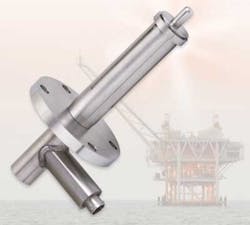
The BMT SSSA is composed of a custom-built linear variable differential transformer (LVDT) in a pressure-balanced, oil-filled enclosure manufactured of corrosion resistant alloy. These sensors typically bolt to flanges or bosses forged onto the pipe sections in which strain is to be measured. Permanent assemblies employ penetrators on each sensor. Diver serviceable assemblies have diver-mateable connectors on each sensor and sensor fasteners. The fasteners are few in number and large enough to be operated by a diver with appropriate tools.
ROVs are more likely to be available than are dive spreads, which usually demobilized once installation and commissioning is complete. While achieving good reliability is still important for an ROV-serviceable system, the risk of losing the system entirely is eliminated because there is always the option of replacing a failed sensor.
Design
BMT's ROV–serviceable SSSA is an evolution of the proven diver-serviceable design. It was necessary to change how the sensor attaches to the pipe in order to make it ROV-friendly. Both ends of the sensor were modified, as were the attachment features that are pre-installed on the pipe. This allows for a single, socket-head screw connection to the pipe on each end of the sensor. This is easily manipulated by an ROV. The design can be installed above water, and also remains diver-serviceable.
BMT believes that it is advantageous for a strain sensor to have a very low actuation force and has designed the SSSA accordingly. This feature results in almost no load on the attachment points as the pipe undergoes strain. In turn, this minimizes dead-band and hysteresis in the measurement system.
To achieve this, the robustness of the sensor is compromised and it must be handled with care – not an attribute of an ROV. Therefore, and because the sensor is inherently both flexible and delicate, an installation tool was developed for the ROV to use. This tool protects the sensor during installation and removal, and also fixes the location of the two ends of the sensor relative to the two attachment points on the pipe. In general, these two features of the tool are intended to compensate for the "lack of finesse" inherent in the ROV's capabilities.
This design allows sensors to be serviced individually, without affecting or interrupting data from the others. This is significant for two reasons. First, it allows the monitoring system as a whole to remain operational, continuing to collect and record data in spite of a sensor failure.
Second, it allows for the preservation of the absolute (as opposed to dynamic) bending or tension measurement when a sensor is removed and replaced. Sensors installed manually prior to the riser's installation can be "zeroed" when the riser is on the back of a vessel, in an unloaded condition.
However, when a failed sensor is replaced by an ROV, there is no opportunity to measure the new sensor's output in an unloaded condition, making it impossible to get an accurate absolute strain value. Because the functioning sensors are never interrupted by the change-out process, the output of the replacement sensor can be adjusted or "zeroed" according to their outputs, which were referenced back to the unloaded state (i.e. "zeroed").
BMT's software processes the sensor outputs by fitting a plane to them collectively. The two orthogonal slopes and the offset of this plane are then used to discern the bending strains (in two directions) and tensile strains. Provided that there are at least three functioning sensors remaining to define the strain distribution plane, it is easy to adjust the zero of a replaced sensor to correspond to that distribution.
A system removed entirety loses its "zero" once it is uninstalled from the loaded pipe; and after being replaced it will only be able to accurately report changes in tension or bending, not absolute values.
Tension and bending
To prove the ROV-serviceable sensor is viable, it was necessary to demonstrate that:
- The new sensor-to-pipe attachment scheme did not impair the sensor's ability to measure strain
- The sensor could be removed and installed by an ROV without affecting the sensitivity of the sensor to strain.
The only way to prove that the sensor-to-pipe attachment scheme for the ROV-serviceable sensor did not affect the accuracy was to perform full-scale bending and tension tests in a laboratory to compare sensor output to the actual pipe strain. These tests were performed by BMT engineers at the University of California's structures laboratory in Berkeley, California.
Because sensors can measure both bending and tensile strain, it was necessary to perform both types of test. The bending test setup was a four-point, simply supported arrangement. A shorter section of the same pipe (with a padeye and a shackle on each end) was used for the tension tests, which were performed in a universal testing machine.
In both the bending and tension configurations, the loads were increased in increments of 20% up to the full-scale test load, then decreased in a similar manner. This up-and-down cycle was repeated twice for a total of three cycles. During the tests, data were recorded from a strain gage bonded to the pipe surface immediately below the sensor (the control, or "pipe strain") as well as from the sensor itself.
The two were compared to evaluate the SSSA performance. A plot of the two measures does not have a slope of 1.0 because the calculation of strain measured by the SSSA uses the nominal dimensions of the pipe, nominal material properties, and a nominal gage length for the sensor itself, all of which are known only imperfectly. Monitoring systems delivered by BMT are calibrated in much the same manner as the tests described here, in order to eliminate these uncertainties (and force the slope to equal 1.0). However, even if a full scale calibration is not possible, BMT has never encountered a situation where the slope differs more than 5% from that calculated with nominal parameters.
To evaluate sensor accuracy, a best-fit straight line is fit to the data using least-squares. The equation of this line then is used to calculate the residual error of each measured SSSA data point – the difference between each data point and the best-fit straight line. The non-linearity or "total uncertainty" of the SSSA's measurement is defined as the maximum of these deviations from the best-fit straight line. In this type of application, test data like these are used to adjust the slope of the linear calibration to be 1.0 exactly. Therefore, the linearity error captures the total uncertainty of the measurement (i.e. there is no bias error).
The test results were excellent. In tension, the uncertainty of the sensor's measurement was less than ± 2.5 με, 0.5 % of the full-scale strain. In bending the uncertainty was less than ± 1.5 με, or 0.4 % of the full-scale strain.
It was also demonstrated that the slope of the sensor's calibration was repeatable within 0.4 %. In other words, when the sensor was removed from the pipe, replaced, and the tests repeated, the slope essentially remained the same. This demonstrates that if a sensor is replaced by an ROV, the user can be confident that the new sensor will have the same sensitivity to strain as the one that was replaced.
Finally, by applying some small fluctuating loads to the pipe, it was demonstrated that the resolution of the sensor was 0.8 με, indicating that the sensor was able to accurately and consistently discern changes in strain greater than 0.8 με (whereas it was unable to respond – at least consistently – to changes less than 0.8 με). The SSSA-measured strain responds to or "tracks" the pipe strain in all instances, the smallest of which is 0.8 με.
ROV demonstration
It was also necessary to prove that an ROV could remove a failed sensor and replace it with a new one. To demonstrate this, it was necessary to actually perform the removal and installation operations in full-scale, using equipment that is available in a typical offshore oil field. Saipem America, the manufacturer of the Innovator ROV, hosted these tests at its facility in Houston.
top, ROV is fastening one of the SSA bolts to tie the sensor to the pipe during the tank test. left, ROV manipulator is pulling the tool away from the sensor.
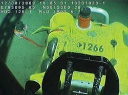
Saipem's facility has a test pool with a crane, and an Innovator ROV with a full control system. The Innovator was equipped with one seven-function and one five-function manipulator for the tests, and Saipem provided the ROV operators. BMT provided a test pipe (which was stood upright in the pool) and the sensor and tool prototypes.
The tests were successful. The ROV removed and reinstalled a sensor on the pipe in less than 1 hour and 40 minutes. A few small modifications were made based on lessons learned during the tests, but in general the concept worked as-designed.
A simple strain test was performed before and after the ROV tank test. A dead weight was hung from the bottom of the test pipe to induce a tensile strain, while the sensor was connected and recording data. Both before and after the test the sensor indicated the same magnitude of strain within 7 με. There is evidence that even this small error was due to changes in temperature during the test, for which no real-time compensation was made.
Factory and site acceptance testing
BMT recently performed a successful factory acceptance test of the first ten ROV-serviceable SSSAs and also performed a site integration test on the customer's equipment prior to load-out for offshore installation.
Future developments
Tank testing demonstrated that the sensor could be installed and removed using the tool and alignment cage; however after witnessing the operation in action, BMT is confident that it would possible to perform the operation without the cage and also to use a simplified version of the tool. This would significantly reduce the infrastructure needed for installing one of these "strain stations." BMT hopes to qualify this design in the near future. Another feature BMT plans to add is a local, ROV-mateable bulkhead connector on the end of the sensor, which would remove the need to have an integral electrical flying lead (EFL).
Acknowledgements
The authors thank the senior management of BMT Scientific Marine Services for funding the R&D effort, and acknowledge the support of BMT Group's R&D Committee.
Editor's note: This article is excerpted from a presentation made at the Deep Offshore Technology Conference and Exhibition 2010.
Offshore Articles Archives
View Oil and Gas Articles on PennEnergy.com