Improved weld assessment method can enhance deepwater pipeline integrity
Thao (Joe) Tran • Ismael Ripoll • Andrew Low • Luca Chinello
INTECSEA
Dan Lee
Heerema Marine Contractors UK Ltd.
Deepwater pipelines transporting corrosive fluids at high temperature and pressure must combine high strength, good strain capacity and corrosion resistance. Corrosion-resistant alloy (CRA) clad and lined pipelines provide an effective solution in these circumstances, and are increasingly used.
The welding challenges associated with these corrosion resistant systems limit applicability of traditional fracture mechanics tools and methods, since they fail to take into account weld strength undermatch. Moreover, the traditional failure assessment diagram-based methods do not handle the more complex strain calculations required for multi-material pipes in complex loading regimes.
The goal here is to outline how these challenges can be overcome through the use of an advanced methodology based on the finite element method, which has been validated through focused testing. A recent example where tangible cost and schedule savings were made using this approach is also presented.
Girth weld integrity
In recent years, CRA-clad and lined pipelines have become an increasingly considered solution to handling corrosive fluids from high-pressure, high-temperature (HP/HT) fields. The use of this option introduces difficulties of demonstrating girth weld integrity through engineering critical assessment (ECA). The available welding consumables for CRA girth welds do not necessarily overmatch the parent pipe, especially at high temperature.
On top of that, at the girth weld, there are high strains caused by installation, especially during reeling, and operation (such as large lateral buckling). These two factors in the multi-material domain push the problem beyond the limits of conventional ECA using the failure assessment diagram (FAD) approach.
As an alternative, the FEA-based crack driving force (CDF) approach has been employed for ECA on many projects. However, the FEA-based CDF approach is expensive, in terms of execution time as compared to the conventional FAD approach. As a result, it is very difficult to perform early sensitivity and optimization studies, especially on very tight schedules.
Moreover, the use of the CDF approach is still under development for CRA pipes, especially for strain-based applications such as reeling installation.
In the absence of a clear codified guidance, installation contractors and design houses have executed a number of strain-based ECA for CRA pipes following published knowledge in the public domain. This practice exposes a pipeline project to risks such as:
- Underestimation of the complexity of the problem
- Disagreement between design houses/installation contractors and the verification parties on “grey” areas, which are not well defined in any standard.
Due to underestimation of the problem complexity, design maturity and test data availability, it is common that insufficient ECA studies (or even no ECA study) are performed during the FEED stage. This increases the risk of having incorrect weld metal and/or incorrect installation approaches selected. Due to the variation in approaches between the design houses/installation contractors and the verification parties, some basic assumptions or even the ECA methodology itself may not be approved. These two factors and the lengthy execution time expose a pipeline project to significant risks related to pipeline integrity and/or installation schedule.
FAD approach
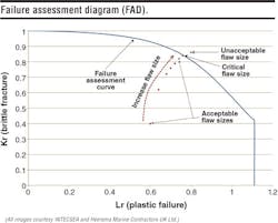
ECA is usually carried out using the FAD method, which is based on the interaction between brittle fracture and plastic failure.
While the failure assessment curve depends on material properties, i.e. tensile properties and fracture resistance of the pipe (assuming that the weld overmatches the parent pipe), the assessment point location depends on the applied loadings, flaw size, and flaw location. If the assessment point is within the failure assessment curve, the flaw size is acceptable; if the assessment point is on the curve, the critical case is obtained. Otherwise, the flaw size is not acceptable. It should be noted that the increase in flaw size (or increase in applied loads) will lead to the movement of the assessment point toward the failure assessment curve. The critical value (of flaw size or applied loading) is obtained when the assessment point lies on the failure assessment curve; this is potentially the optimum solution.
The key advantages of the FAD approach are:
- Computationally inexpensive
- Well documented in standards
- Verified and widely accepted in the industry
- Implemented in ready-to-use tools, such as CrackWise.
These major advantages make the FAD approach easily executable and widely used throughout many subsea pipeline projects. Importantly, the very short execution time (minutes for a case) allows a large number of sensitivity studies as well as optimization of the tolerable flaw sizes.
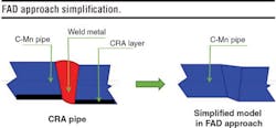
The FAD approach, nevertheless, has some inherent limitations as its essential equations are derived for homogeneous material under uni-directional loadings. This implies two conditions: (i) the multi-material domain must be able to be simplified as a single-material domain, and (ii) the applied loadings should be uni-directional.
In a conventional pipeline project without CRA layers, the above two conditions are easily achieved. Firstly, the C-Mn steel has been used as pipe material for long time, and the weld metal is highly likely to overmatch the parent metal. As such, the bi-material domain comprising of parent pipe and weld metal can be conservatively simplified as a single-material domain with the weld metal replaced by the parent pipe metal. Secondly, the maximum tensile strain is obtained during installation condition, therefore only uni-directional loading is applied.
For a CRA pipeline project in a HP/HT field, the above two conditions are not always achieved. Firstly, the selected anti-corrosion weld metals may not overmatch the parent pipe, especially at high temperature. Similarly, the CRA layer may not overmatch the parent pipe, especially at high temperature. Secondly, the pipe in a HP/HT field is highly likely to experience lateral buckling. In that case, biaxial loading, in longitudinal and hoop directions, is applied.
Workarounds to enhance the FAD approach have been carried out over the past few years. Nevertheless, there is still a lack of consistency on the FAD approach that prevents it from being widely applied to CRA pipes and/or strain-based ECAs.
CDF approach
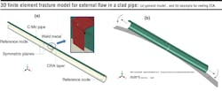
The CDF approach has been developed recently for strain-based and CRA pipe ECAs as an alternative to the FAD approach. The typical detailed model can be seen in the 3D finite element fracture model image, which shows a half pipe with symmetric boundary conditions. Commonly, one end of the pipe is fixed and displacements (either axial or rotational) are enforced at the other end. If the ECA is carried out for a reeled pipe, a displacement control model is utilized. If the ECA is carried out for the operating condition, temperature and internal pressure are applied instead.
The key advantages offered by the FEA-based CDF approach are:
- Ability to model a multi-material domain
- Ability to model all types of material mismatching, including undermatching and partial overmatching
- Ability to model biaxial loading condition, i.e. internal pressure with axial tension.
A drawback of this approach is that a significant amount of time is required for the whole process, including finite element model generation, processing and post-processing. As a result, adopting the CDF approach for ECA has a considerable impact on the project duration. Thus, performing optimization studies and probabilistic ECA using the CDF approach might be unsuitable to some projects, or even impossible in some scenarios.
Improved CDF Approach
INTECSEA has been working to improve the ECA approach for clad/lined pipelines. This methodology has also been independently verified by DNV GL, and has been successfully deployed on recent offshore projects with challenging schedules.
Two enhancements are proposed: 1) automating the finite element model generation and post-processing; 2) extending the application of the FEA-based CDF methodology to the early stages of a CRA pipeline project.
Automated ECA
The common approach to addressing the issue of lengthy execution times has been to optimize the mesh in a finite element model or to use more CPUs in parallel with high-performance computers. Nevertheless, these measures help reduce the model solution time only, and do not necessarily decrease the total execution time, which also includes pre-processing (model generation) and post-processing (result extraction).
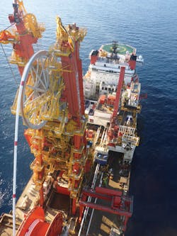
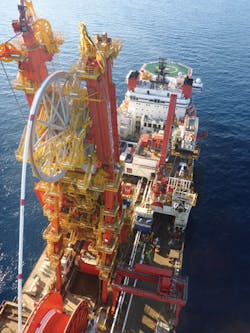
An actual executed project of a CRA pipe by reel-lay installation using Heerema Marine Contractor’s (HMC) deepwater construction vessel, Aegir, and subject to large strains during operation caused by lateral buckling, is provided for demonstration and discussion purposes. Coupled with the high operating temperature, the weld metal partially overmatches the parent pipe material. Due to the weld mismatching, the large applied strains and the multi-material domain at the girth weld, the FEA-based CDF is the most suitable ECA approach for this example.
The example demonstrates that an investment in computing power does not necessarily decrease the total execution time for the FEA-based CDF approach. This is because of the time gaps caused by working hour constraints. Overtime could be considered, however this will result in cost increases. The most efficient solution is to eliminate these time gaps and use an automated tool which shortens the time associated with the pre-processing and post-processing tasks.
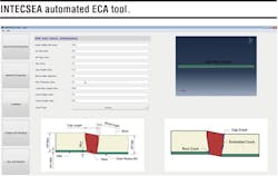
INTECSEA has developed a software tool that is able to perform the entire workflow automatically. All essential input data such as geometrical properties, material properties, loadings and mesh density can be input through the program graphical user interface (GUI), or through a template text file. The tool can be used for C-Mn pipe or CRA clad/lined pipe under installation conditions (S-Lay, J-lay and reel-lay) and operating conditions.
The application of this tool helped HMC to apply more rigorous Level 3C or FEA-based ECA within the schedules available during project execution, so that undue conservatism associated with CRACKWISE methods is avoided.
Commonly, the ECA study is executed near the end of the detailed design phase or at the beginning of the construction phase. This is a common practice from past industry experience with stress-based ECA for C-Mn pipes, in which the FAD-based ECA runs can be performed very quickly for sensitivity studies or optimization studies. Additionally, the weld metals as well as the welding procedures for C-Mn pipes have been well developed and understood over decades of practicing.
Unfortunately, this is not the case for CRA clad/lined pipes. Firstly, the choice of weld metal for the girth welds in a CRA pipeline is limited to the anti-corrosion weld metals, such as Inconel-based or Duplex Stainless Steel (DSS). The tensile properties and fracture toughness of the Inconel-based weld metals are not as high as those of the DSS. Importantly, the material strength degradation of Inconel-based weld metals at high temperature may be high leading to the possibility of an undermatching or partially undermatching weld in operation. On the other hand, Duplex has very good tensile properties and fracture resistance. However, the risk for Hydrogen Induced Stress Cracking (HISC) of DSS for pipeline girth weld has not been well understood and codified yet, therefore rigorous qualification should be undertaken if DSS is considered as the weld consumable.
Secondly, there is no detailed guideline from any standard in the oil and gas industry on the FEA-based CDF approach, although the methodology has been used on many different projects by various design houses and installation contractors. As such, there is a possibility that disagreement on basic assumptions or even on the methodology itself might occur between the design houses/installation contractors and the verification parties.
If the detailed ECA for CRA pipes is carried out near the end of the pipeline detailed design phase or at the beginning of the construction phase, coupled with insufficient ECA study during FEED, the project may face the following risks:
- Incorrect weld metal is selected
- Incorrect installation method is selected
- Final ECA report is not accepted by operators and verification parties on time.
Since the CDF approach is time consuming, any late change in the ECA input parameters, including materials, loadings and basic assumptions, may result in an inadequate study, resulting in a very small tolerable defect size, potentially leading to higher construction and installation costs.
To mitigate the above mentioned risks, it is proposed to perform the ECA during both the FEED and detailed design phases.
A design premise is prepared during early or preliminary engineering. This document contains a detailed description of the methodology and essential assumptions, and is submitted to all parties for agreement. A preliminary ECA is then carried out based on in-house data or based on preliminary test data. This is to provide a preliminary link between design and installation as well as to identify key integrity influencing factors for the pipeline girth weld.
In this document, preliminary information on potential weld metal, strain capacity, possible tolerable flaw size, and suitability of installation methods are provided. This information will provide an assessment of the pipeline integrity and the difficulties to carry out the girth weld, and hence play an important role for the contract between relevant parties. During the detailed design phase, a comprehensive test program is carried out for the selected weld material. The outcomes of these tests are fed into the final ECA to determine the tolerable flaw size. Since the design premise is already approved, calculations would be quite straight forward. Additionally, with a preliminary ECA carried out in the previous phase, the risk of obtaining undesirable results is significantly reduced. Optimization studies can also be performed in this phase to derive the optimized tolerable flaw size that impacts positively on the installation schedule.
Project benefits
The INTECSEA automated tool coupled with an early ECA offer significant benefits in terms of safety, schedule, and cost to a CRA and/or strain-based pipeline project.
First, the proposed improved approach has a positive impact on the safety of the ECA for a pipeline project because it makes the design more robust and increases the checking efficiency. Moreover, with the early development and submission of the methodology to the verification party, adjustments can be made where required, with minimal impact on the project schedule. The safety of the assessment can be further ascertained by carrying out parametric studies, which can be easily done with the support of the INTECSEA automated tool. It should be noted that the tool is designed to be transparent and ease the checking process, rather than to be a “black box.” The automated tool offers many ways to perform the checking for both the input and output parameters. The input parameters can be checked through the program GUI, the input text file, and the Abaqus ‘.inp’ and ‘.cae’ files. The output can be checked through the summary results generated by the tool and by all necessary Abaqus output files including ‘.odb’ and ‘.dat’ files.
Second, the proposed enhancements ensure that the project can be executed on time due to the early ECA activities. Consequently, the final ECA becomes straight forward, with key parameters and assumptions agreed by all relevant parties. This allows the final ECA to focus on the optimization study to derive sets of optimized tolerable flaw sizes associated with various scenarios.
Third, the proposed enhancements can reduce the installation cost with faster welding or construction rate, while maintaining the integrity of the pipeline girth weld. It is noted that the CDF approach is not typically considered during early engineering due to the cost and time constraints. With the automated tool, the preliminary ECA study can be performed efficiently, in terms of cost and schedule, to support the weld metal selection and to identify the key influencing factors for the weld integrity. Moreover, an adequate ECA study in the early stages of a project significantly reduces the risks of incorrect selection of weld metal and installation method, the latter having a large impact on the installation cost if required to change. In addition, with the proposed enhancements, the ECA study can be performed in parallel with the pipeline mechanical design. This could help relax the strain capacity criteria and hence reduce the cost for unnecessary intervention works or mitigation measures.
Conclusion
While the CDF approach offers many advantages for being more accurate and being able to capture biaxial loading effects, weld mismatching, and multi-material domain effects, the significant drawbacks of this approach are the time required by the modelling process and the limited codified guidelines. These drawbacks limit the applicability of the ECA to the early design stages, and valuable sensitivity and optimization studies are not performed.
Consequently, projects might be exposed to the risk of incorrect weld metal and installation method selection to meet very stringent tolerable flaw size. This risk has a significant impact on the project installation schedule and cost.
An improved approach has been proposed and implemented successfully in recent projects. It consists of (1) developing an automated tool to speed up the finite element modeling process and (2) planning for sufficiently early ECA activities. The first enhancement significantly reduces the execution time of the ECA workflow, and therefore offers the possibility of performing very detailed ECA during FEED and early detailed design. The second enhancement is aimed at improving the robustness of the assessment methodology, avoiding incorrect installation method selection and weld metal selection. Together, these two enhancements make the project execution more efficient by reducing the installation cost, and help meet the construction schedule without compromising the integrity of the pipeline.
Acknowledgements
The authors would like to thank Josef Navarro and Will Heaps for their contributions in developing the automated tool. Based on a paper presented at the Deep Offshore Technology International Conference held in The Woodlands, Texas, USA, Oct. 13-15, 2015.
