Smart technologies extending frontiers of subsea projects
Subsea innovations featured heavily in the technical sessions organized by the ONS Foundation. A recurring theme at the virtual event was the drive toward lower-cost, more compact, more efficient, and more remotely operable subsea equipment.
The solutions presented were a response to challenges identified last year by the ONS Technical Committee following the cancellation of the 2020 Offshore Northern Seas conference in Stavanger. Topics included use of new equipment and ‘smart’ IMR to cut subsea opex, and whether this can be accomplished via collaborations; and technologies to help make marginal field tie-ins more profitable, with a reduced offshore installation scope.
Total is pursuing an all-electric subsea future to reduce capex costs of its deepwater projects in particular, and the environmental impact of its operations. “Electrification of our offshore facilities is a key element of our CO2 reduction ambitions,” said Rory Mackenzie, Leader for Subsea Electrical Technologies at Total. Focus areas include reducing the size and weight of subsea infrastructure such as Christmas trees and manifolds, and removal of the electro-hydraulic and chemical umbilicals from the topsides to the subsea wells.
“We see opportunities to improve operational efficiency both through the way the technology operates, and in fewer subsea interventions. There is also an opportunity to improve automation and remote control – this is an inherent benefit of the all-electric system over the typical hydraulic system that we have today.” In frontier water depths beyond 3,000 m (9,842 ft), he added, all-electric technology is not subject to the same hydrostatic pressures. “It also enables ultra-long step-outs which can realize the potential of subsea-beach architectures… These would allow development of fields far from the coast, without the need for surface [host] installations, which could be economically viable at $50/bbl.”
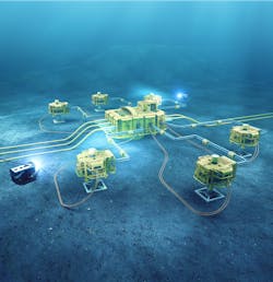
Critical to Total’s vision is lighter and simplified subsea equipment that is also robust and reliable. A resident AUV with a docking station, equipped with an automatic pipeline monitoring system, would perform regular inspection of pipes and other facilities without the need for assistance from a surface vessel. Elsewhere on the seafloor, a central unit would distribute electrical power transmitted via an underwater cable to all subsea production/process systems: one of these is Springs, designed to remove sulfur from seawater prior to reinjection into the reservoir. New-generation composite jumpers would connect the water injection line to the injector wells: should damage occur, a solution based on epoxy resin wrapping could be applied to provide temporary repairs to underwater lines. Injection chemicals would be stored in a tank on the seafloor, with interventions performed where needed by ROVs deployed from a surface vessel.
An automatic subsea pig launcher, placed at the end of the subsea production line, would be operated from the coast or from an unmanned vessel. The launched pig, circulating with production back to the coast, would provide regular cleaning of the pipe. During shutdowns, the single production line, heated to prevent formation of hydrates, would be sized according to requirements, based on multiphase flow simulations performed with LedaFlow software. Also on the seafloor, a multiphase pumping system would provide the energy needed to boost production over 150 km (93 mi) or more to the coast. At the onshore reception terminal, a surface pig receiver would be operated by autonomous robots.
All these technologies are under development, Mackenzie pointed out, via various JIPs involving contractors such as Aker Solutions, Baker Hughes, OneSubsea and TechnipFMC, with additional support from Chevron, Equinor, and Norwegian majors Aker BP and Lundin Energy. There is also a need to standardize requirements for the various technologies, he stressed, and this should be implemented in the next release of the relevant industry standards.
Subsea power distribution
For most subsea boosting projects to date, topsides power equipment is used to control and operate the subsea boosting pumps. According to Ola Jemtland, Manager New Product Development at TechnipFMC, the equipment, typically installed inside a power control module, tends to be large and heavy (more than 100 tons), and requires available space on the platform. The associated cost and constraints may be too great to justify a brownfield investment.
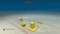
TechnipFMC’s Subsea Power Distribution (SPD) system takes most of the equipment to the seafloor, potentially at 60% lower cost than topside-hosted subsea boosting. The SPD station includes a subsea transformer and several 2-MVA Variable-Speed Drives (VSDs) to control and operate the subsea pumps. The design is compact and scalable to a wide range of boosting applications, and can operate in water depths of up to 3,000 m.
The subsea VSD, based on a WEG, field-proven topsides VSD, houses the same power and control components inside a one atmospheric, nitrogen-filled canister. The sole change to the original VSD architecture is the mechanical arrangement of the power electronics and control unit, with passive conductive cooling provided through the canister wall. The subsea transformer is also based on a proven WEG topsides transformer, with the internal components fitted into an oil-filled, pressure-compensated housing, and dual-barrier oil volume compensators arranged within the transformer module. Since the subsea VSD is a “standard building block” and the subsea transformer a separate, scalable unit, there is no need for new product qualification for each individual project, Jemtland claimed.
The configurable design allows for operation of multiple units to increase output power/redundancy. For example, if three VSDs operate a 3.5-MW subsea pump, and one of the units fails, the other two could still provide up to 3 MW shaft power. Each subsea VSD is also equipped with input/output contractors for electrical protection and isolation. The multi-winding subsea transformed is connected via an umbilical to the topsides power supply.
Jemtland outlined one scenario involving an 8-MVA subsea SPD controlling two mudline pumps, each with shaft power close to 2 MW. Two VSDs in parallel mode operate each pump, connected via a single, three-phase, ROV-operated electrical power flying lead. The drive units each weigh less than 15 t, and can therefore be installed using lightweight lift vessels. The total footprint occupied by the SPD in this case is around 10 x 5 m (33 x 16.4 ft), with a total weight of 120 t - however, smaller or larger versions are also feasible, depending on the power needs.
Liberty E-ROV
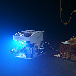
Oceaneering’s Project Manager Arve Iversen updated progress on the Liberty E-ROV, following its first 18 months of operation for Equinor’s IMR services fleet in the Norwegian North Sea. During this time the vehicle performed 28 missions, starting in June 2019 with periodic inspections at the Statfjord D and C platforms, followed by similar campaigns at Troll A and B, Gullfaks A and C. Other tasks included operation of a gas line flapper valve; riser inspection at Valemon; riser monitoring and well commissioning at Snorre A; and leak detection at the Åsgard B platform in the Norwegian Sea.
The Liberty E-ROV is operated from a seabed garage, with a 500-kWh battery and a 1,000-m (3,281-ft) tether, i.e. a 1-km working rang around the garage. A surface communications buoy, also tethered, provides a 4G connection between the vehicle and the onshore control center. Permanent deployment of the ROV subsea, without the need for a host vessel to sail in and out, has led to savings of 22,000 t of CO2 over a year, in addition to financial savings in vessel time.
Template/Manifold
Baker Hughes has developed an integrated template/manifold system, the Multi Well Flow Base (MFB), as a lower-cost, faster-to-construct solution for subsea tiebacks. According to Systems and Technology Leader, Hasan Ali Mahmood, subsea templates have been in use offshore Norway for decades and designs have been standardized over several years. “But however optimized they are, they still look big and heavy. Our idea was to challenge the specifications, come up with something more compact.”
Compared with earlier, complex templates – typically 26 x 22 m (85 x 72 ft), and weighing 650 t – the subsequent standardized versions for Norwegian fields delivered a 29% smaller footprint – 23 x 19 m (75 x 62 ft) – and a 15% reduction in size (580 t). However, the MFB takes downsizing to a new level, cutting the footprint by 35% to 19 x 15 m (62 x 49 ft), and the weight by 40% to 350 t. The typical ‘integrated template system’ (ITS) for Norway, Mahmood explained, features independently installed manifold, Christmas tree and choke bridge modules. These separate modules require interface tolerance loops, with all the associated complexity and cost, and use of multi-bore tie-in connectors. This results in fabrication complexity.
With the traditional ITS the modules must also come together on the seabed, with the ability to re-connect and disconnect. For this to happen, all must be tested, and the need to double up on steel connections with multi-bore connectors entails substantial fabrication of small-bore tubing to ensure that everything fits together.
The MFB, which is compatible with Baker Hughes’ MVXT and MXHT Christmas tree ranges, is based on a tree with an insert-retrievable choke, with manifold pipework fixed to the template structure.
It is essentially a four-well flowbase, with the manifold fixed on the template. As Mahmood pointed out, “manifolds are reliable products, it’s very rare to need to retrieve one.” The tree for the manifold connection is a vertical land-out with and a mandrel connector, with no separate choke bridge module.
“As for the distribution system, we have changed the solution so that instead of using multi-bore lines, we have pre-laid hydraulic and electric flying leads, installed by an ROV on the seabed. This simplifies the construction process: it uses pre-defined and existing flying lead product lines, leading to a cleaner, simpler layout from a fabrication perspective. The flowbase is on a mud mat, so you can pile the foundations if conductors are not in place.” The MFB can be placed on the seafloor via a single-lift installation: “with no manifold to come later, big savings can be made on installation time and cost. Flanges and flange connections are available for divers in water depths of 100-150 m (328-492 ft), but the system can also be scaled up to be diverless.
This solution, he concluded, “is lower on capex and opex, with 230 fewer tons of steel on the seafloor, saving around 400 tons of CO2 in the construction process. It’s a simplified system, which accelerates time to first oil… and with a shorter testing period as there are fewer modules to interface with each other. The valves are flanged to allow for flexibility in fabrication. When the total system is standardized, it can be delivered in 12-15 months.” Currently Baker Hughes is constructing five MFBs, four to be installed in the current quarter and one toward the end of this year.
Composite jumper
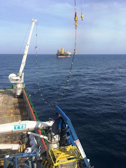
Charles Tavner, COO of Magma Global, highlighted two applications of the company’s all-thermoplastic M-Pipe product in marginal fields. One is a 6-in., 30-m (98-ft) jumper, replacing a steel hydrocarbon jumper in the North Sea. “It’s a much simpler crane installation, with no need for a lifting frame or metrology and a much shorter lead time from order to installation.”
The second is a project to replace collapsed flexible jumpers off the Adriatic coast. This is for a smaller diameter HP injection line for sour service, connected to 2 x 40-m [131-ft] jumpers with a 25-year design life at 5 ksi, in a water depth of 1,000 m (3,281 ft). The solution was designed and installed eight weeks after Magma received the order.
“People ask, when we use such premium input materials, how do we cut the cost of the product?” Tavner said. His answer was that Magma’s simpler construction process uses less material to achieve the performance as non-bonded flexibles. As for the fully installed cost, Total performed a comparison for a West African jumper system. The steel jumper had a lower overall materials cost, but when fabricated, the cost of the jumper and the fully installed cost were much greater than for M-Pipe. This was due to the complexity of the required lifting frame and the need for a larger installation vessel, the added weight of the steel product, and the complexity of fabricating non-bonded flexible end-fittings.
With M-Pipe, the simplicity of manufacture is down to use of only two materials: carbon fiber and PEEK, and a single manufacturing process, which is the same irrespective of the diameter or length of pipe. So, the standardized product is good for marginal fields, he concluded.
About the Author

Jeremy Beckman
Editor, Europe
Jeremy Beckman has been Editor Europe, Offshore since 1992. Prior to joining Offshore he was a freelance journalist for eight years, working for a variety of electronics, computing and scientific journals in the UK. He regularly writes news columns on trends and events both in the NW Europe offshore region and globally. He also writes features on developments and technology in exploration and production.