History of semisubmersible platforms provides guidance for future deepwater projects
Richard D’Souza, Richard B Offshore
Shiladitya Basu, KBR Consulting
Tirtharaj Bhaumik, KBR Consulting
Malcolm Sharples, Offshore Risk & Technology Consulting Inc.
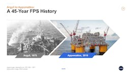
The first oil and gas production from a floating platform began in 1975 from the Argyll field in the central North Sea in about 80 m of water. The platform was a converted second generation semisubmersible Mobile Offshore Drilling Unit (MODU). The use of floating production systems grew as industry had to move farther offshore to find new sources of oil and gas to replace declining production from shallow water fields.
Today, there are over 300 floating production platforms in operation, the majority of which are semisubmersible Floating Production Systems (FPS) and Floating Production Storage and Offloading Platforms (FPSOs).
As the offshore industry begins to emerge from the downturn, deepwater operators are increasingly looking to floating production systems (FPSs), notably semisubmersible production platforms, to advance their field development projects. By some estimates, there could be as many as five additional FPS field developments in the Gulf of Mexico by 2025.
The semisubmersible design has become increasingly popular as the industry has moved out farther into deeper waters. Examination of three of Gulf of Mexico deepwater projects – Na Kika, Atlantis, and Delta House – can illuminate some of the key design and installation issues facing operators of semisubmersible production facilities.
Na Kika
The Na Kika development is in the Mississippi Canyon, 225 km offshore, in water depths ranging from 1,670 m to 2,300 m. It began producing in late 2003 from the first purpose-built FPS in the GoM, almost 18 years after the discovery was made. It was a groundbreaking achievement, setting many technology firsts and deepwater records. It was developed by Shell and BP under a joint operating agreement (JOA) executed in 1998, with Shell responsible for delivering the FPS and BP for its operation after startup. The project was sanctioned in September 2000.
The initial phase of the development consisted of six widely dispersed oil and gas fields and 10 subsea wells. The wells are tied back to the centrally located FPS with offset distances ranging from 8 km to 42 km. Whereas each individual field is non-commercial, collectively the six have an estimated recoverable reserve of 300 MMboe.
The Na Kika project was perhaps the most challenging subsea development attempted at the time with unique flow assurance challenges related to a combination of extreme water depths, distributed well layout, variability in produced fluid properties, long well offsets, low reservoir temperatures, and difficult seabed topographies. The flow assurance challenges led to a “belt-and-suspenders” approach that included pipe-in-pipe looped flowlines, electric heating, gas lift, methanol injection and dead oil displacement of oil flowlines to prevent the formation of hydrate and wax deposits. Processed oil and gas were exported via 18-in. and 20-in. diameter export lines. Between the production and export lines, there were 11 risers initially attached to the FPS.
In 1996, the Na Kika development plan consisting of a central host and subsea tiebacks from the six fields was established and the JOA between Shell and BP was executed in 1998. A thorough assessment of all viable host options (TLPs, spars, turret moored FPSOs and FPSs) was conducted. An FPSO was dismissed because of regulatory concerns regarding storage and shuttling of produced oil, expansion constraints of the turret, and technical concerns regarding the swivel and riser systems. A spar platform was dismissed because of installation, future expansion and intellectual property issues. Converted and purpose-built FPSs were assessed, but the conversion concept was dropped because of air gap and structural fatigue concerns, as well as uncertainty of conversion and operating costs. Shell settled on a purpose-built FPS as it provided the best combination of capital cost, wave response suitable for supporting steel catenary risers (SCRs), and flexibility for expansion of topsides and SCR additions for future tiebacks. Further, the hull and deck configuration closely resembled five large TLPs that Shell had successfully built and were operating in the GoM at the time.
The Na Kika FPS hull is a four-column, ring-pontoon configuration. The pontoons are of square cross-section and the columns square with rounded corners to facilitate shipyard fabrication. The column tops are interconnected by a structural UCF that structurally decouples the hull and topsides deck structures, permitting the respective designs to proceed independently and concurrently. Shell had previously used the UCF concept for its Ursa TLP.
The global sizing of the hull and mooring, on the critical path of the project schedule, began in January 2000 and a final configuration frozen in May 2000. The hull displacement is 58,400 mt and the hull steel weight is about 18,000 mt. Shell used an in-house program to optimize cost against different column and pontoon configurations and sizes to satisfy functional, hydrostatic and hydrodynamic performance and regulatory requirements. The final hull size provided payload flexibility for future expansion that included provision for 15 spare riser porches for future SCRs. A key design objective was to optimize the hull configuration for minimum vertical motion at the riser porches. The maximum roll/pitch angle in a 100-year storm was constrained to 7 degrees for operability and survival considerations. Hydrodynamic performance and air-gap were verified by wind and wave model tests.
Four topsides deck modules span the column tops and house the process, power, utility, accommodation and subsea support equipment and consumables required to operate the platform. The modules were designed to minimize inter-module hook-up. The process and two subsea support modules are truss designs while the quarters and power module are “stress skin” designs. Each module is placed on four elastomeric pads located on the column tops. The pads isolate them from the hull dynamic loads while restraining them from platform lateral motions. The inboard open area supports a sliding bridge crane with a heavy-duty chain jack to pull in SCRs. The topsides, designed to process 110,000 b/d of oil and 425 MMscf/d of gas, are powered by five gas turbines generating 24 mw. Topsides and deck operating weight is about 18,000 mt.
Shell had executed its five TLP platforms with separate contracts for hull and topsides fabrication and one for topsides/hull integration. For the Na Kika FPS, Shell decided to combine the individual contracts into a single turnkey contract. There were three Korean yards capable of doing so at the time. After a round of competitive bidding Shell awarded a turnkey contract for FPS construction, integration and transportation to Hyundai Heavy Industries (HHI) in early 2001.
The hull and topsides modules were fabricated independently, and the topsides modules interconnected and then lifted and integrated onto the preassembled hull using the Superlift technique pioneered by HHI. The four topsides modules were fabricated on eight large lifting beams and the four hull modules on a set of skidways adjacent to the Superlift site. Four large jacking towers were erected on the interior of the topsides. Thirty-eight strand jacks located on the tops of the lifting towers were attached to the lifting beams and the topsides raised 50 m. The four hull sections were skidded underneath and welded out, and the topsides then set on the column tops. The total operation was completed in 20 days.
Upon completion of integration and pre-commissioning activities, the platform was skidded onto a double barge unit, towed to a deepwater site and floated off. It was then floated on to the Mighty Servant 1 heavy-lift transport vessel, sea-fastened and then dry transported to the host readiness site at Kiewit Offshore Services (KOS) in Texas. The FPS was delivered in mid-April 2003 versus a planned date of December 2002.
The Na Kika project maintained a strong focus on regulatory approvals and the relationship of the two primary regulatory authorities, the Mineral Management Service (MMS) and the United States Coast Guard (USCG). Shell for many years had dealt directly with USCG and MMS by applying its own best practices (which also included pioneering requirements for human factors), rather than rely on the industry minimum standards set by classification societies. About 90 approvals were required prior to start of production which went relatively smoothly with one exception. Just before the construction award of the FPS to HHI, the USCG informed the project that the 42,000 barrels of dead oil Shell intended to store in the hull pontoons was to be considered “cargo” similar to that of an FPSO. The “cargo” designation presented a set of issues related to concerns arising out of FPSO and tanker regulation, sorting out of potential applicable International Maritime Organization (IMO) initiatives then under discussion. USCG did rule that only the outboard sides of the pontoons needed to be double-sided for collision protection as did the pontoon tops to protect against dropped objects. By then, Shell had already committed to full double sides for the dead oil storage tanks.
The Na Kika FPS was moored in 1,932 m of water, at the time the deepest permanently moored platform in the world. The previous record in the GoM was ExxonMobil’s Hoover spar platform installed in 1,370 m of water that began producing in 2000. Shell conducted a rigorous set of trade-offs for the mooring system arrangement before settling on a 4 by 4 semi-taut, chain-wire-chain suction pile configuration. The trade-offs included evaluating polyester rope, submerged buoys and drag anchors. A 4 by 4 configuration was picked over a 4 by 3 as it provided manufacturing and installation advantages at about the same cost. Installation trade-offs showed that installing the mooring system with a heavy-lift crane vessel was competitive with installing by anchor handling vessels, but with lower weather-related risk.
The mooring system was designed to API RP 2SK criteria using time and frequency domain analysis methods to check component strength in the intact and one line damage conditions in a 100-year return period storm. They also checked that the maximum line loads in the 1,000-year return period event were checked to see that they did not exceed line breaking strength.
The “on-vessel” mooring hardware consisted of a single chain jack mounted on the top of each corner column with a self-contained hydraulic power unit to hook-up and pre-tension all four mooring lines on the column. Bending shoe fairleads with an integrated chain stopper were attached at the keel. The “off-vessel” hardware consisted of 124 mm diameter studless Grade 4 platform chain (including corrosion and wear allowance), 114 mm diameter torque balanced spiral strand wire rope with polyethylene coating, and 114 mm diameter Grade 4 studless ground chain connected to a 4.3 m diameter by 25.3 m long steel suction pile.
Heerema’s dynamically positioned SSCV Balder pre-installed the off-vessel mooring system and assisted with the hook-up to the on-vessel hardware on the FPS. The Balder had been recently fitted with a mooring line deployment winch capable of installing mooring leg components in these sizes and water depths. With its spacious deck and large carrying capacity, the Balder was able to pre-lay all 16 lines with little weather downtime in 2002. The FPS was hooked up to the risers and moorings in 2003, followed by the commissioning of the FPS, subsea and export systems.
From their past experience of executing complex TLP projects Shell recognized that the key to minimizing delays and recycles common to such projects was to focus on interface management. They established early, direct interfaces between hull global, structural and marine systems design teams inclusive of regulatory approvals, and with the topsides, mooring, and subsea system and construction teams.
First oil was achieved in November 2003, some 38 months after project sanction, just four months later than the scheduled start-up. This was an excellent result considering the complexity of the development and the number of technology firsts and deepwater records that were set along the way.
Atlantis
In 1999, BP and co-lessees embarked on an ambitious program to develop four major fields in the deepwater Walker Ridge area of the GoM: Holstein (with co-lessee Shell), Mad Dog (with co-lessee BHP and Chevron), Thunder Horse (with co-lessee ExxonMobil) and Atlantis (with co-lessee BHP) in that order. Their execution schedules overlapped with first production targeted between 2004 and 2006.
The Atlantis field was discovered in 1998 and the development began production from a large FPS host platform in October 2007. Unlike Na Kika, which required unitizing six small, dispersed reservoirs to justify a commercial development, the Atlantis field was estimated to have recoverable reserves in excess of 600 MMboe in a single reservoir. The reservoir is located beneath the Sigsbee Escarpment with a mountainous topography sloping from 1,340 m to 2,135 m of water. About 60% of the reservoir is buried under a thick canopy of salt which challenged seismic technology capabilities available at the time to characterize the reservoir and its recoverable reserves with a high degree of confidence.
With poor seismic imaging, a handful of appraisal wells in a structure 24 km across and without dynamic well data, there was a high degree of uncertainty in predicting well rates and ultimate reservoir recovery. But the thick reservoir intervals and excellent rock permeability enabled the project to get the green light to advance to the select phase in February 2001.
BP decided to develop Atlantis in phases beginning with the south side of the reservoir (not underlying the salt canopy and relatively flat topography) developed first. The development plan was to produce from 16 subsea wells clustered around four subsea manifolds and four water injection wells. The production wells were tied back with five flowlines and SCRs to a large production quarters (PQ) FPS, moored in 2,133 m of water below the escarpment to avoid mooring system design issues and flow assurance concerns with upward leading flowlines. The wells were to be drilled and completed by a dedicated fifth generation MODU, the Discovery Driller 2. The field architecture provides the flexibility to respond to reservoir uncertainty and allows for expansion of future development phases to the north. Produced oil and gas are exported via SCRs and tied into the Mardi Gras trunk lines.
Selection of the floating host platform began in February 2001. The subsurface team had settled on a maximum production rate of 200,000 b/d of oil, 180 MMscf/d of gas and 75,000 b/d of water injection. The resulting topsides load, as well as the SCR loads, required a large host platform. The Select team rapidly narrowed the contenders to a PQ and production drilling quarters (PDQ) spar and FPS. After several months comparing relative costs and risks of the four options a PQ FPS was selected because:
• It provided the greatest seabed layout flexibility for well placement and future expansion
• It reduced the project execution risk by minimizing extensive offshore installation work (vs. the spar option)
• It eliminated simultaneous drilling and production operations risk (vs. the PDQ option)
• It reduced project execution complexity (vs. the PDQ option)
BP decided to have a dedicated MODU, Discovery Driller 2, drill and complete the subsea wells and also install subsea manifolds and make manifold to flowline jumper connections. The select phase was completed by year end 2001 and the hull and topsides FEED began in early 2002. The Atlantis project was sanctioned in November 2002.
The Atlantis FPS hull is a GVA-designed four-column, ring-pontoon configuration similar to the Na Kika hull with one crucial difference. The column tops are interconnected with a buoyant box deck which serves to:
• Structurally integrate the hull
• Provide reserve buoyancy in the event of loss of column buoyancy
• House non-hazardous topsides equipment and accommodation.
GVA pioneered its design in the 1980s in response to the tragic loss of the Alexander Keilland accommodation vessel in the North Sea and the subsequent Norwegian regulatory requirement to provide reserve buoyancy to compensate for the loss of column buoyancy. BP picked GVA to design the Thunder Horse PDQ hull as it was the industry leader in large purpose-built FPS designs proven in hostile North Sea conditions. The company had also designed the largest FPS at the time (Asgard B FPS at about 85,000 mt displacement) and were known for its shipyard friendly designs derived from its shipbuilding roots.
GVA began the FEED of the GVA 27000 (mt of topsides payload) hull and mooring system in early 2002. The as-built hull displaced nearly 90,000 mt which at the time was then the second largest steel hulled FPS after the Thunder Horse FPS (130,000 mt).
Mustang Engineering (now Wood) was contracted by BP to be the project services and topsides engineering contractor for all four BP’s host platforms to standardize topsides equipment and transfer “lessons learned” from one project to the next. The topsides consisted of three major modules; process, power generation (60 mw) and compression (28,000 hp) arranged in a horseshoe configuration around a central moon pool on the deck box. In a lesson learned from Na Kika, chemical and dead oil tanks were placed on a topsides porch rather than in the hull. The moonpool was equipped with a heavy-lift device to haul in the SCRs and hook up 40 m long spool pieces to the riser baskets for direct vertical access to the riser. There was space and weight allowance to add a fourth future module. Topsides weights and center of gravity were continuously monitored during fabrication to be in compliance with the established Not-To-Exceed (NTE) weight and center of gravity envelope of the hull design. The as-built dry topsides weight of the three modules was 12,810 mt, within 1% of the FEED weight. Topsides detail engineering began in November 2002 and fabrication commenced in June 2003.
BP elected to adopt the traditional GoM contracting approach of building the hull in a Far East shipyard; the topsides in a GoM fabrication yard; then performing the topsides lift and integration to the hull quayside with one of the available heavy-lift cranes at Ingleside, Texas. The hull construction contract was awarded to Daewoo Shipbuilding and Marine Engineering (DSME) shipyard in Okpo, South Korea; the topsides construction to McDermott International (that fabricated all four of BP’s Walker Ridge platform topsides as part of the standardization initiative); and the integration contract to KOS. Hull construction began in December 2003. The completed hull was dry transported from Korea in March 2005, arriving in the GoM two months later. Fabrication of the three topsides modules began at McDermott’s Morgan City yard in June 2003 and the mechanically completed modules shipped to KOS for integration on to the hull. The modules were lifted onto the deck box in June 2005 by KOS’s Heavy Lift Device (HLD) followed by quayside hook-up and pre-commissioning. The sail away to the Atlantis site scheduled for later that year was postponed until August 2006 for reasons explained below. The FPS was hooked-up to the 12 preset mooring lines, followed by the SCR and umbilical hook-ups. First oil commenced in October 2007.
The Atlantis project benefited from the experiences and lessons learned from BP’s preceding Thunder Horse project and Na Kika project in partnership with Shell. The project team appreciated the importance of regulatory issues and the potential for costly rework and delay if the MMS and USCG were not fully engaged at an early stage and kept continually updated. An experienced regulatory manager was appointed with a suitable budget and authority to engage the design, construction and operations teams, providing regular briefings together with a regulatory execution manual. Subjects of interest included specific content of a marine operations manual; an in-service inspection plan; an emergency evacuation plan; a construction portfolio, classification society approval requirements and management plan, manning and licensing/training, installation and transportation, as well as required on-board documents to be on board. Presentations to the team were also made on vendor coordination with classification society or the USCG for certified components ensuring they were approved prior to shipping. Leadership was provided on how to do callouts in the yard and tracking of outstanding punch lists. The communications plan with regulators was emphasized, and opportunities were provided for the USCG representative at the Korea site to meet with and agree on decisions made with the Corpus Christi-based USCG representative. This was all designed to minimize re-work upon arrival of the hull in GoM where a difference of interpretation could delay the project. Likewise, MMS was encouraged to conduct inspections in the yard ahead of startup to avoid delays to first production.
Regulatory issues were mapped to provide the Construction and Operations team with a documented process between USCG Headquarters, USCG Technical Approval office, USCG New Orleans, and USCG at sites in Korea and USA. Joint surveys were specified with an assembly of a joint punch list for ABS, USCG, and other parties, and a process for regulatory queries to be speedily dealt with by the regulatory manager within a specified timeframe. The regulatory manager and vendor coordinator were required to be in close contact with the regulatory team to prevent schedule slippage.
Despite rigorous risk assessment and hazard identification processes conducted by BP, the Thunder Horse and Atlantis projects confronted with and solved significant and largely unforeseen challenges inherent in executing fast-track frontier projects. Several issues on the Thunder Horse development impacted those on Atlantis which followed closely behind. The first was in July 2005 when the Thunder Horse FPS, awaiting riser hook-up and final commissioning at the site, had to be evacuated ahead of Hurricane Dennis. When personnel returned after the passage of the storm they found the platform with an extreme list as seawater had entered certain column and hull compartments. The initial cause of the list was traced to the ballast control systems that allowed shifting of ballast water throughout the hull enabled by the incorrect installation of ballast discharge valves that resulted in entry of seawater into the hull. The problem was exacerbated by water moving through large open penetrations for electrical conduits in inter-hull bulkheads that were designed to be water tight. The GVA box deck configuration provided the reserve buoyancy that prevented the potential loss of the FPS.
As a result, a thorough marine assurance review was conducted on the Atlantis FPS which was at the KOS yard at the time and changes made to its bilge and ballast system and electric conduits. In addition, fiber bond pipe work in the firewater and bilge systems were replaced with more traditional copper-nickel and video technology smoke-detectors replaced with traditional smoke detectors. Instrumentation was included to monitor platform motions, mooring line tensions and metocean conditions and the data transferred to shore via satellite and fiber optic cable so that the condition of the platform could be monitored from shore following an evacuation. These modifications to the Atlantis FPS delayed its sail away to the site by almost a year.
A seawater leak caused a hydrate plug to form in the tie-in spool of Atlantis’ gas export line to the Mardi Gras trunk line. It took several months to remediate the plug which delayed the start of gas export by two months after first production.
Despite these significant challenges, Atlantis was a commercial success. When the first well flowed in October 2007, oil production rates were in excess of 20,000 b/d and by mid-January 2008 six wells were producing 110,000 b/d. Atlantis completed the year 2009 with the plant operating efficiency of over 98%.
The challenges and successes with the Atlantis FPS paved the way for BP’s future deepwater projects. When BP decided to recycle the Mad Dog 2 development in 2013 to substantially reduce project break-even cost they replaced the spar platform with an FPS in part because of BP’s execution and operating experience with the Atlantis FPS. The Mad Dog 2 project was sanctioned in 2016 and first oil is expected in 2021. In January 2019, BP approved a $1.3-billion Phase 3 expansion of the Atlantis field.
Delta House
Operated by LLOG, the Delta House field is in the Mississippi Canyon block 254 in about 1,370 m of water. The host platform is a purpose-built FPS displacing about 39,000 mt with an 11,000 mt topsides operating payload. It is designed to initially produce from three “anchor” fields, ranging in distance from 10 km to 22 km, and capable of accepting production from additional fields within tieback distance. Initial production is from six subsea wells connected to three four-slot manifolds. Two pairs of looped flowlines tie the manifolds to the host with 6-in. and 8-in. diameter SCRs. Produced oil and gas is exported from 16-in. and 18-in. diameter risers respectively. The development is notable for a non-traditional execution and financial approach that enabled LLOG to achieve first production in just over three years from discovery of the first field in February 2012.
Normal practice for a development is to fully appraise a discovery before selecting and sanctioning a plan of development. LLOG turned conventional wisdom on its head with its development approach. In 2011, the company reviewed its deepwater GoM prospect inventory and determined that it had the potential for multiple “hub” class prospects mostly in the prolific Miocene reservoirs. The leases on some of these prospects were close to expiring, providing the urgency for LLOG to try a non-traditional approach.
It decided to unitize multiple sub-commercial fields producing from standardized four slot manifold subsea wells and tie them back to a central host platform. The reasoning was that the speed and flexibility of pre-drilling and completing subsea wells and tying them back to a PQ host outweighed the advantage of drilling and intervening from a dry tree host. The company chose a semisubmersible as the PQ host based on its success with the Exmar designed Opti-EX FPS deployed on the Who Dat field that began production earlier that year (2011). The Opti-EX FPS is a “standard” design with the flexibility to adapt the hull configuration to a range of water depths, topsides payload and riser systems. It also has a unique topsides structural arrangement that provides a single large deck to set and interconnect topsides modules and equipment at the “ground level” and integrate it in a single quayside lift with an HLD available in the GoM.
To accelerate cycle time to first production LLOG and partners approved the engineering of the Opti-EX 11000 (mt of topside payload) with a nameplate capacity of 80,000 b/d of oil and 200 MMscf/d of gas in October 2011 in anticipation of a discovery. The process equipment was designed to accommodate a range of expected oil densities and gas oil ratios. The export system was designed for peak production of 100,000 b/d of oil and 240 MMscf/d gas. LLOG concurrently began a process of selecting “partner” fabrication yards to build the hull and topsides. After an abbreviated selection process they contracted HHI in South Korea for the hull fabrication and KOS in Ingleside, Texas for the topsides fabrication and integration by January 2012.
That same month, LLOG and partners made their first Delta House discovery followed by a second, larger discovery in May 2012. They assessed and discarded the possibility of tying these fields back to existing third-party hosts because of flow assurance and ullage concerns. They determined that the most profitable development would be provided by an FPS host for three anchor fields, the two discoveries plus a third operated prospect adjacent to a discovered lease. This development option provided superior economics but could not meet the company’s economic hurdle at the low end of the reserve uncertainty range. Not wanting to drill additional delineation wells LLOG decided on obtaining private equity financing.
At the time there were several examples of host platform and export pipelines (infrastructure) owned by unaffiliated third parties, freeing the producers to use available capital for well drilling and completion. In these transactions the third party provides the capital cost for the infrastructure and collects a tariff from the producers based on the volume of production. In May 2012 LLOG began negotiating with ArcLight, one of the infrastructure providers, which would assure them a reasonable return at the low end of the reserve range and for the producers to not pay an inordinate tariff if the high end materialized.
The Delta House FPS is a four-column, ring-pontoon hull supporting a distinctive integrated truss deck on the column tops. The single deck supports the topsides modules and equipment required for the nameplate production capacity with room for expansion. The pontoons are rectangular with rounded corners and the columns are five-sided, also with rounded corners. The hull configuration and its 30 m draft provide the targeted dynamic response in extreme seas to support the production and export SCRs.
The column, deck and pontoon primary shell, bulkhead and truss structures are aligned to provide an efficient global space frame. Hull structural plating, framing and compartmentation have resulted in an efficient topsides-to-hull steel weight ratio. Freeboard to the underside of the deck structure is sufficient to provide a positive air-gap in a 1,000-year return period storm. There are no external hull penetrations and seawater ballast is drawn from caissons attached to the inboard shell of the columns. It also has a unique on-pontoon riser porch and adapter system that enables SCR pull-in from a single winch and diverter sheaves.
The platform is anchored by a 12-point chain-polyester-chain mooring system and 4.9 m diameter and 25.9 m long, 135 mt suction piles. On-vessel chain jacks adjust for stretch and creep of the 10-in. diameter polyester rope.
The deck is a truss structure integrated with the column tops to provide global strength. The single flat deck permits maximum flexibility for setting topsides modules and equipment skids and interconnect them on the ground. Open deck area and spare load capacity is available for future expansion. Particular attention was paid by the topsides designer and fabricator to weight and center of gravity control throughout the design and fabrication cycle to ensure that the lift capacity of the HLD was not exceeded.
The hull and topsides are designed to meet relevant BSEE and USCG regulations. Regulatory approvals were managed by DNV GL.
First steel for hull construction was cut at the HHI yard in March 2013 within a month of project sanction as the engineering and contractual arrangements were completed ahead of sanction. The hull was assembled in HHIs large dry dock in one piece and delivered in March 2014, one year later. It was dry-transported by the Dockwise Treasure heavy-lift transport vessel (with a temporary truss structure connecting the column tops) to the KOS integration site in Texas where it arrived in May 2014.
Construction of the topsides truss structures and modules began at the KOS yard in December 2012. The topsides was mechanically completed on the ground and lifted onto the hull by the HLD in a single lift. At 9,300 mt it was the largest lift ever conducted by KOS. The hook-up to the hull and pre-commissioning was completed in three months and the fully integrated platform sailed to the Delta House site in September 2014.
Meanwhile, 12 suction piles were designed, fabricated and pre-installed along with the ground chain and polyester rope by Intermoor about a year earlier. Intermoor employed a modified anchor handling vessel at a significant cost-savings over dynamically positioned heavy-lift crane vessels used by Shell and BP for Na Kika and Atlantis. The host platform was hooked up to the pre-set moorings in October 2014. Hook-up of the six SCRs and final commissioning followed and first production began on April 2015, 28 months after project sanction and 38 months after discovery.
LLOG and partners’ bold decision to begin engineering the FPS before a discovery was made and the aggressive scheduling to first production produced its share of challenges.
The assay of the reservoir fluids from the discovery showed that the produced crude light ends and gas heavy ends were outside the range of the fluid properties that the topsides were designed for, producing more propane and butane than anticipated. These fluids are difficult to manage as they can cause oil export lines to exceed the Reed Vapor Pressure and create slugging in the gas export lines. The fix was to add a condensate stabilization unit that would allow injection of the liquids into the sales gas pipeline. The topsides weight budget, already tight, was exceeded by the addition of this unit. The design teams made adjustments to the design such as integrating some skid mounted equipment and relaxing design basis criteria which resulted in a 450 mt weight savings but added to the fabrication cost.
The single deck design provided the topsides engineering and fabrication teams the ability to make design-while-build adjustments. The hull construction at HHI was rushed to meet the tight dry dock slot for final hull assembly but ultimately did not impact the quality and schedule.
Two factors enabled LLOG to pull off a remarkable feat of managing an aggressive fast-track deepwater project. One was the financing arrangement with the private equity partners ArcLight and Blackrock providing capital to build the host facility and the export pipelines before a discovery was made, enabling LLOG to sign fabrication contracts for the FPS shortly after the first discovery well was drilled. The second was the choice of the Opti-EX 11000 FPS as the host facility. The proven Exmar standardized design, a smaller version of which was used to develop its Who Dat field, provided the confidence and the lessons learned to keep the project on track.
Smaller, simpler, standardized
A trend, already in progress, will be to build smaller and simpler FPSs that will lower capital costs, accelerate cycle times to first production and increase cost and schedule predictability. In the GoM about 80% of discoveries can be developed with an FPS processing about 80,000 boe/d. The larger fields will be developed in phases by two repeatable FPSs built sequentially rather than by a single large FPS. The benefit of this approach is twofold: one is that the first phase requires lower capital investment and cycle time (a necessity as offshore projects compete for capital allocation with onshore shale projects), and the other is that it provides valuable subsurface information to optimize the second phase. The second phase will also benefit from standardization and lessons learned efficiencies from the first phase.
The industry will also embrace “standardized” developments that will include platforms strategically sited to provide efficient host locations for multiple field developments. A standardized FPS is repeatable with design adjustments for reservoir and site-specific conditions. In the GoM, Shell, LLOG and Anadarko have realized significant commercial benefits with this approach.
In 2015, industry identified bespoke specifications as a chief culprit of cost inflation, supply chain delays and quality issues. Analyses showed that simplifying and standardizing specifications could improve total value of a deepwater project by 30%. The industry embarked on a series of JIPs aimed at streamlining procurement by simplifying and standardizing specifications and drive a structural reduction in upstream project costs. As an example, the JIP 33 Capital Project Complexity Initiative begun by a consortium of operators and suppliers in 2015 showed the potential for 10% to 20% reductions in equipment capital expenditure, 40% schedule compression and enhanced quality and reliability.
In another example DNV GL in 2015 initiated a JIP with major Korean shipyards targeted at formalizing common and global best practices for components and equipment such as tertiary structures, bulk materials, piping and electrical etc. and harmonize industry, Operator and maritime standards. Operators have undertaken various forms of “rebaselining” to strip projects to their basic functional objectives that resulted in workable, operable system at 25% lower capital cost based solely on scope reductions. We predict that these trends toward simplification and standardization set in motion in 2015 will become institutionalized.
Digitization, automation and manning
The ongoing digital transformation has the potential for significant capital and operational efficiencies. The offshore industry has been slow to embrace digital opportunities but is now incentivized to fully realize its vast potential. A recent white paper highlighted a striking fact: an average offshore platform has 30,000 sensors generating data but less than 4% is used to make operational decisions. Engineers are drowning in data but are unable to find the information they need when they need it. This is about to change with digitization. Operators estimate that by 2050, a full embrace of available digital technology has the potential to reduce lifecycle cost across all oil and gas resource classes by 30%. Digitization is projected to underpin 25% of increased resource recovery and one-third of capital and operating cost reductions.
Conclusion
Today, large purpose-built FPSs provide the foundation for many large-scale deep and ultra-deepwater developments around the world. The functional and technical aspects of the semisubmersible platform design have made it the second most utilized floating production platform after the FPSO.
FPS designers have responded to the recent drop in oil and gas prices by simplifying and standardizing designs that have enabled significant reductions in break-even costs of deepwater developments to compete with onshore shale projects. The future of the FPS will be sustained by digitization and automation technologies that will continuously improve design and operating efficiencies, reduce manning and drive down capital and operating costs. •
Acknowledgment
This article has been excerpted from the paper titled “The Semisubmersible Floating Production System: A 25-year Technical and Historic Retrospective,” presented at the 126th Annual SNAME Conference, Oct. 30-Nov. 2, 2019, in Tacoma, Washington. The paper includes sections on Field Development Planning and Floating Host Selection, Regional Databases and Cases Histories for the North Sea, GoM, Brazil and the Far East and evolution of FPS Hull, Mooring and Riser Systems and Governing Codes and Regulations. Reprinted with the permission of the Society of Naval Architects and Marine Engineers (SNAME).