Case study: Dissolver/dispersant supports increased production on North Sea asset
The formation and buildup of scale substances can result in loss of production due to issues such as plugging, corrosion, flow restriction and emulsions. Efficient ways to handle oil wet solids during production water reinjection (PWRI) is an inherent challenge for the industry. The use of production chemicals can be applied to recover damage to PWRI systems that would otherwise have required vessel intervention to clean flowlines.
For many years, an operator in the North Sea had been using seawater injection for pressure support, with produced water discharged to sea. However, the operator’s strategy changed, and seawater injection was halted. Instead, all produced water was reinjected via subsea wells, with a subsea flowline transporting the water to these wells from the host platform.
At this time, H2S and oil levels began rising in the produced water due to problems with separation. Iron sulfide, reservoir silicates, barium sulfate scale and biomass were found within the hydrocyclones. These issues were controlled by the application of flocculants and monthly cleaning of separation equipment. The subsea water injection flowline was also experiencing increased pressure drop because of fouling in the injection line, resulting in lower injection capacity.
The continued capacity reduction of the subsea water injection flowline, and the potential for total occlusion of this line, were considered the most significant threat to the remaining reserves in this field.
ChampionX Corp. was tasked with developing a customized chemical cleaning program to prevent ongoing fouling and generation of H2S in the operator’s PWRI systems. The typical treatment program would require large volumes of chemical, so the ChampionX team worked to design a solution with fewer logistical hurdles.
Laboratory assessment
Focused on treating the root cause of topside separation and injection line fouling that was causing the biogenic H2S generation, the ChampionX team assessed whether it was possible to reduce iron sulfide formation and improve oil in water volumes topside through application of an H2S scavenger to the subsea production wells.
Effective methods for cleaning the water injection line were initially evaluated via batch application of chemicals, such as hydrocarbon solvents, mutual solvents (hydrocarbon removal and water wetting), dilute acid solutions and THPS solutions (iron sulfide dissolver), chelants (barium sulfate dissolvers) and oxidizing agents, such as hypochlorite (biomass dissolvers). While this showed an acceptable degree of performance, there were several challenges to consider:
- A large amount of chemical was required for the treatment due to the flowline volume;
- Logistics of collecting the spent chemical that could not be injected into the well;
- Duration of time over that the injection line would be out of service (resulting in a full field shutdown) to allow pumping and soak periods; and
- The aggressive nature of some chemical stages with respect to the materials used in construction of the subsea flowline and wells.
This led to an alternative cleaning program being evaluated, which could be continually injected at a lower rate to remove fouling within the produced water line and help prevent additional fouling.
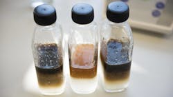
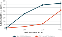
Based on the composition of the fouling material in the injection line, the proposed formulation contained a non-THPS dissolver (near neutral pH) for removal of the iron sulfide (Figure 1), combined with a corrosion inhibitor that would act as a surfactant to reduce interfacial tension. This treatment would ensure trapped oil became mobile to assist the disaggregation of the iron sulfide/hydrocarbon accumulations.
In addition to this cleaning program, a 1,000-ppm glutaraldehyde batch treatment was applied for 90 minutes every five days.
Assessment of the microbiological activity within the produced water was made using molecular methods, including adenosine triphosphate and adenosine monophosphate quantification and quantitative polymerase chain reaction (qPCR). Due to high counts of sessile bacteria, a treatment was recommended that showed good performance.
Field performance
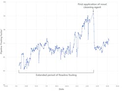
A field trial of the non-THPS dissolver/surfactant was set up, and the restriction “fouling factor” along the water injection flowline was trended to compensate for the variation in frictional pressure drop as a result of variation in flow rate. Fouling material samples were also tested and analyzed prior to and during the trial to determine if the composition of the material had changed due to the application of the chemical. There was a significant reduction in the fouling factor with the onset of the injection during the three-month trial (Figure 2).
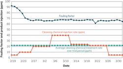
The performance of the injected chemical from five to 40 ppm is shown in Figure 3. To reduce the risk of displacement of partially dissolved biomass, oil and sulfides into the injector well, the cleaning chemical was injected at a slow rate (5 ppm) with an associated risk of reduced injectivity. This resulted in an almost instant reduction in the fouling factor.
Increasing the treatment rate from five to 10 and on to 20 ppm showed a steady reduction in the fouling factor as the iron sulfides and hydrocarbon were swept from the injection line surfaces. No improvement was observed when the concentration was increased from 20 ppm to 40 ppm. The optimal cleaning action was achieved at 20 ppm, as the fouling factor did not decline above this rate. Notably, even at 5 ppm, the chemical prevented refouling of the system.
Analysis of the recovered solids after the cleaning chemical application showed a reduction in the iron sulfide percentage within the recovered solids but an increase in the barite (barium sulfate = scale). While the proportion of barite in the sampled material rose, the total amount of foulant reduced over time. This is not due to additional scale formation but rather removal of the iron sulfide, meaning that the unreacted scale solids make up a higher proportion of the remaining deposit.
The hydrocarbon content of the recovered solids post-chemical application also showed a significant reduction, suggesting the surfactant properties of the cleaning chemical above 5 ppm were able to mobilize oil from the deposit.
During the cleaning chemical injection period, microbiological growth determined from “studs” within a side stream unit showed significant reduction, with evidence of cleaning chemical and glutaraldehyde synergy. The surfactant package of the cleaner would help to penetrate the biomass and cut channels into it, which allows the biocide access to more surface area of the sessile colonies.
The application of the novel cleaning chemical program resulted in the following changes to the PWRI system:
- Produced water injection rate increased from 729 cu. m per hour to 777 cu. m per hour (a 7% increase). While this is not full recovery of the injection potential, it is a significant improvement;
- Injection pressure reduction from ~50 bar to 40 bar (a 20% decrease, despite injection rate increasing). Therefore, a reduction in the energy required by the injection pumps;
- Increased production, as the injection line fouling was reducing reservoir voidage replacement; and
- Reduced risk as the injection line was able to take more of the produced water.
Improvements in H2S management within the produced water will lead to less iron sulfide generation in the topside, resulting in fewer solids entering the flowline with the produced water. Along with fewer solids and less oil in water, fouling was reduced within the flowline.
Long-term sustainability
For efficient operations, it is vital to prevent fouling and generation of H2S and iron sulfide in PWRI systems. The innovative technologies applied on the North Sea asset provide opportunities to improve efficiency and minimize waste by reducing the energy needed to operate injection pumps, lowering the total cost of operation, helping improve production gains and avoiding unbudgeted costs.
By continually injecting the customized chemical treatment, a significantly lower volume of chemicals (27,000 liters) was required compared to batch treatment (59,476 liters), thereby improving the carbon footprint of the operation by requiring less chemical to be manufactured and injected and fewer chemical tanks to be shipped (12 versus 26).
References available upon request.
Editor's note: This article is an abridged version of SPE-209478-MSD paper presented at SPE International Oilfield Scale Conference and Exhibition in May 2022 in Aberdeen, Scotland.


