Managing drill floor practices, equipment important in quick-drilling Thai wells
Editor's Note: Good no-nonsense drilling practices sometimes get overlooked for more complex high-tech engineering solutions. Although necessary in some situations because of specific technical demands, more cost effective solutions can be realized with creativity and innovation. In this issue, Offshore continues the presentation of practical and functional well construction practices and techniques.
Santa Fe mobilized the Compact Driller jackup from West Africa to the Gulf of Thailand in July 1998. Since that time, oil and gas discoveries have been numerous, but the geology is very difficult to interpret, the reservoirs are small, and the wells have a limited production time of only a few years.
To make these marginal prospects commercially viable, operating companies, in this case Thaipo Ltd. And their successors as operators of the B8/32 License Area, Chevron, have turned to technology and innovation to increase performance and minimize drilling costs. An open-minded approach, it questions the methods we have traditionally used to drill wells and produced some impressive results.
The operator initially looked at well design for the small reservoirs being produced, and concluded that slimhole wells would be adequate. A typical well design used 9 5/8-in. casing as a surface string to approximately 1,200 ft, then a 7-in. intermediate string to 5,000 ft, and open-hole slim-tubing completions to 10,000 ft and 12,000 ft. After "slimming" the well design, the next task was to maximize the number of wells per platform.
Aboard the platforms, an innovative well design was developed to run two 9 5/8-in. surface casing strings in one 30-in. conductor casing. This entailed directionally drilling a 26-in. hole and then running two strings of 9 5/8-in. casing, one after the other into the same 26-in. hole.
One string is run plus or minus 300 ft shorter than the other to facilitate separating the wells when drilling out the next hole section. Both casing strings were cemented through the deepest string, with a shoe track being created in the shorter string by allowing cement to back flow 100 ft into the casing by a special valve arrangement.
Unique drilling practices
On exploration wells, Chevron also felt time savings could be made on the 9 5/8-in. surface string, and invested in a casing "drill-in system." Two different methods were tried - successfully. One style was to run a mud motor, under-reamer, and bit inside the 9 5/8-in. casing shoe. Mud was pumped down the casing from the top drive, powering the motor, under reamer, and bit ahead of the casing. The assembly was then retrieved on drill pipe, with the shoe, at the required depth.
The second simple system used a special drilling casing shoe, allowing the casing to be rotated and drilled to the desired casing depth. These systems saved considerable time and also eliminated the problems of trying to find the 12 1/4-in. hole on the seabed when running 9 5/8-in. casing in 240 ft of open water, without subsea cameras.
Santa Fe and Chevron worked together to devise a wellhead system for exploration wells that simplified hanging of the intermediate 7-in. casing string. This involved creating a high-capacity tensioning system coupled with a surface mandrel wellhead, eliminating both the troublesome MLS and time taken to separate the blowout preventer (BOP) and wellhead to install surface casing slips.
Typically, a whole section will be drilled, the casing run and landed with a landing string that allows the rig to immediately connect the running tools to a separate circulating line. The casing is then circulated and cemented concurrent to the drill floor skidding to the next well. The BOP can then be nippled up and ready to test, by the time the cement job on the previous well is completed.
Other time savers
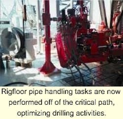
Great effort was made to identify any operation that could be undertaken outside of the critical operating line. One of the most time-consuming operations identified for a jackup moving on these typically fast 10-day wells was pipe handling. The Compact Driller reduced this to a largely off-line activity by installing a hanging spin-torque unit. This is essentially a small hanging version of an iron roughneck. The advantage is that it can be hung in any position, allowing drill pipe to be safely picked up and broken down in the mousehole during drilling. This has proven to be a significant time saver. Santa Fe is also working to increase the capacity of the derrick to allow the jackup to do field moves with drill pipe racked in the derrick.
Another area identified as a candidate for offline activity was electric wireline operations. The Compact Driller originally had the wireline unit mounted on top of the housing quarters. This essentially meant that while wireline operations were ongoing, the rig cranes were shut down with a wireline stretched across the middle of the rate.
A new platform structure was pre-fabricated onshore, installed on the rig during normal operations, and the wireline unit spotted accordingly. The wireline operation was then confined to an area on the port side, and cranes could work boats and layout strings of casing on the cantilever for the next well section during wireline logging operations.
Chevron and Santa Fe constantly benchmark operations to identify timesaving opportunities and encourage innovation for the personnel on the rig. While it is easy to propose various operations that can be performed concurrently, it takes innovation, organization, and commitment from the supervisors and the crews on the rig to carry out this multi-operation workload safely.


