Lazy-S risers offer advantages in the ultra deep
Keith Shotbolt, Consultant
In ultra deepwater -- beyond 1,500 m (5,000 ft) deep -- riser plus umbilical weight off a floating production vessel (FPV) can total many thousands of tons. Weathervaning FPSOs have turret swivel bearings with limited load capacity. Riser system weight applied to a disconnectable FPSO should be kept low because after disconnect, the turret buoy has limited self-buoyancy.
Riser configurations with integral buoyancy include:
- Lazy-wave, with a series of small buoyancy collars around the overbend
- Free-standing multi- or single-line tower, with a large buoy at the top of the steel column
- Lazy-S, with a tethered buoy between the lower J-catenaries and the upper U-catenaries.
Lazy-wave risers
Lazy-wave flexpipe risers are in place with many FPSOs around the world. The lazy-wave overbend with multiple small buoys usually is set fairly deep to minimize riser movement from current and wave action. As depth increases beyond 1,000 m (3,280 ft), setting lazy-wave riser buoyancy at >50% of total depth leaves significant weight applied to the turret.
The disconnectableStybarrow FPSO is operating in 825 m (2,707 ft) water depth off Australia using lazy-wave flexpipe risers. A major FPSO turret designer has estimated that the maximum practical depth for lazy-wave flexible risers to a disconnectable turret is around 1,500 m, depending on the numbers of lines and lateral current velocity.
Shell plans to install the first S-shaped steel catenary risers (SSCR) or steel lazy-wave risers to a weathervaning FPSO on its BC-10 field in 1,780 m (5,840 ft) water depth off Brazil. The SCR and the SSCR are unlikely to be used with a conventional disconnectable FPSO because they apply too much weight to the turret buoy, and they probably need a flexjoint at the turret connection, which is difficult to access. SBM-Atlantia has recently proposed the MoorSpar concept, which would have sufficient buoyancy to support SCRs, and a swiveling arm for mooring an FPSO.
Tower risers
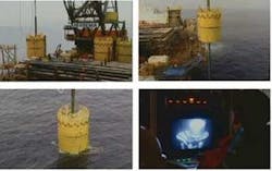
The ‘vertical steel tower + flexpipe catenary jumper’ type riser, described in US patent 4,182,584 (granted in 1980), has a large buoyancy tank at the top of the tower. TheGirassol FPSO off Angola came on stream in 2001 through circular bundle tower risers, and the Plutonio FPSO also has a 1,260 m (4,134 ft) long bundle tower riser containing multiple lines. All bundled tower riser lines must usually be incorporated on ‘day one’ because it is difficult to add extra lines. It may be necessary to incorporate expansion relief for individual lines in this type of construction if they operate at different temperatures.
2H Offshore introduced the single line offset riser (SLOR) at the Kizomba field, which started producing in 2005. The concentric offset riser (COR) version has an outer pipe around the riser pipe, and the annular space between them can be used for transporting lift gas.
Lateral current may cause a large ‘leaning’ deflection, and/or vortex-induced oscillations of the buoyancy can and tower. Anti-VIV strakes will increase current drag and overall deflection from vertical. 2H and Subsea7 introduced the Grouped SLOR concept to overcome problems of widespread seabed connections, and buoyancy can and mooring line spacing with a plurality of SLOR risers. It may be possible to control lateral deflections of Grouped SLORs in current by installing guy lines to the upper riser guide frame.
A flowline to a single or multi-line tower base requires a connecting spoolpiece, which needs:
Tower risers do not usually include umbilicals, which have been arranged separately in either lazy-S or lazy-wave configurations.
Petrobras plans to install five single-line free-standing hybrid risers (FSHRs) to its disconnectable Cascade-Chinook FPSO slated for the US Gulf of Mexico in around 2,500 m (8,202 ft) water depth. These risers are similar to the SLOR-type described above.
Lazy-S risers
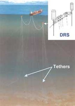
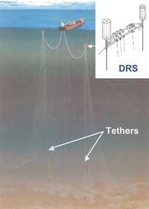
Coflexip installed the first single lazy-S flexpipe riser in the North Sea in 1984. The upper U-shaped catenary absorbs vessel and wave motions, and the tethered mid-water buoy maintains the lower J-catenary and touch-down point almost static. Multiple lazy-S riser systems were installed to North Sea semi-FPVs at Ivanhoe/Rob Roy (on stream 1989) and Buchan fields (operating via lazy-S since 1999).
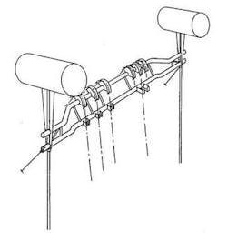
Many FPSOs operating worldwide have multi-line lazy-S risers arranged over tethered buoyant mid-water supports. A 2001 survey of 277 flexpipe risers operating in the North Sea and West of Shetlands offshore area showed that approximately 50% were arranged in the lazy-S configuration. In water depths to 300 m (984 ft), the buoys are often constructed as large horizontal tubes or cylinders, which can be de-ballasted by displacing a water-fill with air or nitrogen. Arches may be positioned over the tubes to support riser pipe overbends at larger radius. The associated tethers are made from synthetic fiber rope or steel chain.
Deepwater riser support
In March 1999, Foster Wheeler presented its deepwater riser support (DRS) concept at the Deepwater Pipeline Conference in New Orleans. The DRS for DLSRs comprises a 20-50 m (66-164 ft) long beam-type support for lower catenary hangers and overbend arches, supported by buoyancy tanks that are rigidly attached above each end. The assembly is held at setting depth by just two main tethers in a single plane.
In a DLSR system, the J-catenaries can be flexpipes, umbilicals, integrated production bundles (IPBs), SCRs, or towed bundles. SCRs and steel bundles can only be used where the J-catenary is sufficiently long to allow the steel pipe to behave in a substantially flexible manner. Spare slots along the DRS will allow extra risers to be added when required.
In deepwater, with the DRS submerged 100-300 m (328-984 ft), the total J-catenary tension can be more than 10 times the upper U-catenary tension. The DRS minimizes the tendency for hanging riser weight to rotate the beam assembly by:
- Small offset of the lower catenary hangers
- Stabilizing high set buoyancy cans.
Tether materials
Tether material options, to cater for increasing water depth and riser weight, include fiber ropes, casing-type tubulars, and tension leg platform (TLP)-type tendons. In ultra deepwater, TLP-type tendons can provide sufficient axial stiffness (E x A) to minimize length change under variable riser load, e.g. adding extra risers, or between hydrotesting and drying a gas export riser. TLP tendons have proved to be very reliable in service.
null
Riser load in 3,000 m water depth with four production risers for two pigging loops, two umbilicals and two water/gas disposal/export lines could reach up to 4,000 metric tons (4,409 tons), needing buoyancy tanks of about 12 m (39 ft) diameter x 26 m (85 ft) height. Each tether will carry approximately 500-metric ton tension, which remains practically constant in all weather conditions because the buoyant structure is fully submerged below the wave zone. TLP tendons have been designed for around 1,000 metric tons (1,102 tons) tension in calm conditions, with variation in the maximum storm wave from 32 up to 2,500 metric tons (35-2,756 tons).
The DRS, with only two tethers, keeps tether and related anchor costs to a minimum.
DRS installation
TLPs are usually constructed by pre-installing the tendons with temporary buoyancy tanks before lowering the hull structure down onto them.
DRS construction is likely to begin by installing the two tethers with top buoyancy tanks, pre-tensioning the tethers by de-ballasting the tanks, and then lowering and attaching the riser/umbilical support beam to extension members under the buoyancy tanks. In the DRS case, the buoyancy tanks are permanent to maintain tether tension and to support the risers.
The large cylindrical buoyancy tanks may require strakes to overcome problems with vortex shedding in high current conditions. If possible, the tanks should be set below the high current zone.
Horizontal buoyancy tanks
Another design option, which may be less susceptible to vortex-shedding problems and may ease tendon top alignment, would be to mount the tanks horizontally. If necessary, a temporary spacing frame with two inverted V or U-shaped saddles could be lowered over the tanks to ensure correct spacing and orientation prior to lowering and fixing the riser support beam.
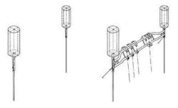
STEP 1. Install tendons and tension them.
STEP 2. Lower riser support beam and lock in position.
Reducing the overall height of the structure by mounting the tanks horizontally may be advantageous if the beam is set at relatively shallow depth. The horizontal tanks should have internal bulkheads to divide the length of each tank into partitioned compartments. This will allow controlled distribution of air/nitrogen when the tanks are partially de-ballasted. More or less gas content fore or aft will allow ‘trimming’ of the structure to design orientation under varying load as riser catenaries are added.
Guy lines
Lateral forces, due to ocean current drag and/or catenary riser top angle, will tend to move the tethered buoyant structure away from its design position. After the structure has been attached to the main tethers, it may be necessary to attach up to eight guy lines in a 4 x 2 pattern to maintain the riser support structure in its design position, vertically above the tether anchors. The guy lines are best constructed from low submerged weight synthetic fiber rope, each having approximately 100-metric ton (110 ton) load capacity. They can be attached to the structure by upper light chain portions pulled through chain stoppers.
Flow assurance
Riser-base-gas-lift (RBGL) has been fitted to at least five multi-billion dollar oil developments in depths from 1,000-1,350 m (4,429 ft) off West Africa, and at least two developments in depths from 1,300-1,850 m (4,265-6,070 ft) in the US Gulf of Mexico.
Water temperature below 1,500 m (4,921 ft) depth at all latitudes is less than 5° C (41° F), which makes trace heating attractive to avoid or clear line blockage (wax/hydrates) if flow stops. Shell/Intec installed pipe-in-pipe SCRs and flowlines at Serrano-Oregano, Habanero (750 m or 2,461 ft), and Na Kika (1,850 m or 6,070 ft) developments, where a support vessel with power source and cable can provide electric heating when required. RBGL to SCRs has needed a separate lift gas supply line to a seabed sled and spools to injection tees.
Total installed Technip’s IPBs with integral electric heating, temperature monitoring, and RBGL for eight 12-in. (30-cm) risers at Dalia (1,350 m) development, and re-ordered IPBs for Pazflor. An alternative to an IPB may be a flexible riser pipe with a piggy-back 3-in. (7.6-cm) gas lift line, but would not benefit from lift gas heat transfer to produced fluids. IPBs and flexpipes do not require anti-VIV strakes.
Subsea pumps are being installed at satellite manifolds to boost the pressure of produced fluids. These pumps need high voltage cables for power supply, which add to the overall riser/umbilical system weight.
Lower J-catenaries that include any of these flow assurance methods can be suspended from a DRS, which can also support a gas lift manifold and electrical distribution boxes to simplify U-catenary connections to an FPSO turret.
About the author

Keith Shotbolt gained 32 years experience in oil and gas projects and is now an independent consultant. After SPE papers on riser design and flow assurance while with Brown & Root (1983) and Bechtel (1986), Foster Wheeler encouraged him to present a paper on Deepwater Riser Options in New Orleans and Aberdeen in 1999. Questions/comments on this article can be addressed to [email protected]
Advantages of a deepwater lazy-S riser (DLSR) system in ultra deepwater include:
- Neat arrangement of a relatively large number of risers and umbilicals
- Minimum riser and umbilical weight applied to the FPV
- Installation uses proven TLP tendon technology and method
- No concern about riser base connections and flowline expansion
- Adaptable to suit the latest methods for RBGL and trace heating
- The overbend location of all risers and umbilicals is controlled by the tethered buoyant support, which can be set well below the wave and high current zone, and guyed to restrict lateral deflection from any remaining current.