Isolate reservoirs during underbalanced operations
By Frank Hartley
Engineering Editor
Operators have long needed a multiple-use tool that could isolate reservoirs during underbalanced operations while easing the complexity and expense of those operations and increasing safety levels.
Initial attempts to meet these goals focused on subsurface safety valves (SSV). These valves worked well at first. Because SSVs are reusable, they helped in the tripping and drilling stages of well construction and were not strictly a liner/completion deployment system. However, SSVs had a major disadvantage. Setting depth was limited by the hydraulic activating system used by the valves, imposing significant depth limitations on lateral length in underbalanced horizontal wells. As a result, SSVs were far from the perfect solution.
Second-generation systems focused on packer deployment. A retrievable packer/ bridge plug would be set at the required depth in the casing to set up the downhole lubricator. The packer would then be retrieved by the liner and run to the bottom. This system allowed versatility in setting the depth. However, retrievable packer/bridge plugs were solely a liner deployment tool and did not eliminate the requirement to snub on trips.
More recently, efforts have focused on a third approach - the creation of a working valve designed to satisfy the requirements of the job rather than the standards set for the SSV. This new approach has enabled a working valve to be built that will fit into traditional hole and casing sizes and still perform effectively.
Safer, more economical approach
The new Halliburton Quick-Trip valve was created to meet the need of an apparatus that could safely and conveniently facilitate underbalanced operations. The valve uses a collected latch sleeve assembly that is displaceable in the valve and controls the opening and closing of the valve's closure assembly.
When a tool, such as a drill bit, is conveyed into the valve, a shifting sleeve secured on the tool with shear pins engages the latch sleeve assembly. Further displacement of the tool causes the shifting sleeve to be displaced, opening the valve. Once the valve opens, the shifting sleeve is released from the tool and left within the valve to protect the sealing surfaces. On the trip out, the bottomhole assembly (BHA) retrieves this sleeve and the valve closes.
This series of actions allows the valve to safely isolate a formation intersected by a wellbore from the remainder of the wellbore while the tubular string is being tripped in or out. It also allows the valve to be installed near the formation without compromising its operability or reliability.
Design practicality
In designing this valve, the theme was to maximize its usefulness. Accord-ingly, casing clearances and hole sizes used in traditional well design were considered. A valve that requires changing hole or casing sizes can significantly increase the well's overall cost and ultimately will adversely affect the net present value of the field.
The design allows operators to either cement the valve in the hole as a permanent part of the casing string or to place the valve in a temporary workstring, use it in one well, then pull it out of the hole, redress the tool, and reuse the valve on another well. This significantly reduces the capital cost of the tool, allowing that tool to be amortized over a project rather than per well. In such cases, however, the workstring may be susceptible to backing off during the drilling process, and this risk should be weighed against potential cost savings.
Well design considerations
Placement of the valve should be determined during the planning phase of the well. The process involves examining and prioritizing a variety of situations and conflicting parameters, then planning for the worst-case scenario. Buckling and casing wear are particularly important concerns, and the use of several reliable computer programs can accurately analyze both. To avoid such risks, the valve is placed in a section of casing where it will be subjected to the least interference by the drillstring.
Lab and field tests
Early laboratory and field-testing began in 1997 and were conducted to qualify the initial design. Lab tests consisted of manually opening and closing the valve and circulating 16-ppg cement and 14-ppg drilling fluid. A cementing wiper plug was also run through the valve to ensure that it would pass through the valve without problems. At this point, minor modifications were made in the flapper pivot area to allow flapper and sleeve retraction while high-solids fluids were present. After lab and flow tests were completed, three separate field tests were run in actual wells.
Additional tests were performed in mid-2001 on the 7 5/8-in. and 9 5/8-in. valves and allowed verification of the improvements made to the valve's design. The valves were assembled and manually actuated in the lab and pressure-tested to certify a desired working pressure of 3,000 psi.
Final tests were performed in a test well where the valves were actuated several dozen times and subsequently pressure-tested to verify that they could still hold working pressure. Further design improvements resulted from these tests. Specifically, shifting sleeve shear screw material and design were changed to allow greater life and to prevent downhole junk from being potentially created after each actuation.
As a result of this testing and design improvements, the valve available is certified to a working pressure of 3,000 psi and can repeatedly and reliably actuate downhole.
Economic advantage
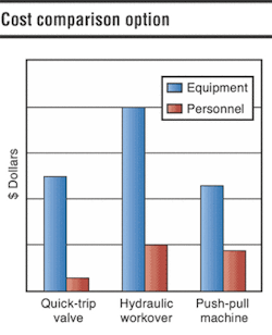
The valve is a more cost-effective option and provides superior performance over either a push-pull machine or a rig-assisted hydraulic workover (HWO) unit. In permanent installations, it offers an additional cost benefit because it can be used for the life of the well. This allows future well interventions to benefit from the safety and efficiency of the valve while keeping the well underbalanced at all times. A push-pull machine or HWO would need to be used separately each time an intervention is carried out. Comparisons have proven a way to reduce operating costs, improve efficiency, and enhance safety in underbalanced drilling and completion projects.


