DRILLING TECHNOLOGY: PART II - Casing drilling with directional steering in the US Gulf of Mexico
PART II: This is Part II of a two-part series on casing drilling, focusing on challenging surface hole sections in the US Gulf of Mexico. Part I, which appeared in January, dealt with applications on two conventional wells.
The directional programs involving casing drilling for South Timbalier 37 wells A-12 and A-13 in the US Gulf of Mexico were benign, but the experience gained while drilling them indicates that wells with a more challenging directional program can be drilled with a casing drilling system.
Before drilling these wells, it was not clear what build rates could be achieved in the soft formations. Also, there was a concern that the drilling torque could be too high for the casing connections in wells with higher inclinations. A table shows the slide yields (total curvature/slide interval) achieved in well A-13 with the 1.83 degree bent housing motor. The average slide yield between the depths of 331 ft and 3,705 ft is 4.3 degrees/100 ft.
Experience with the casing drilling system with smaller casing sizes indicates that the build rate normally increases as the inclination increases. Even in the soft US Gulf of Mexico formations, it seems reasonable to anticipate using the casing drilling system with 9-5/8-in. casing in wells that have build rates as high as 3 degrees/100ft and possibly higher. Initially, the percentage sliding might be quite high, but would decrease as the inclination increases.
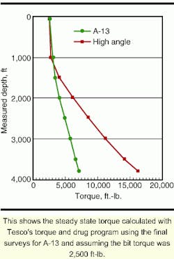
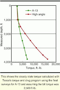
The drilling torque on A-13 increased to about 7,500 ft-lb at the end of the well for intervals that drilled smoothly, but torque peaks as high as 11,000 ft-lb were experienced while drilling a hard stringer at 3,200 ft. An accompanying figure shows the steady state torque calculated with Tesco's torque and drag program using the final surveys for A-13 and assuming the bit torque was 2,500 ft-lb.
Also shown in the same figure is an estimated torque for a hypothetical well with a more demanding well profile typical of other wells drilled in the US Gulf. This hypothetical well path nudges away from other wells between 300 and 500 ft, builds at 3 degrees/100 ft from 500 ft to 1,200 ft, then builds at 4 degrees/100 ft to 60 degrees, and holds 60 degrees to 3,800 ft measured depth (MD). As indicated in the figure, this well path would require 16,000 ft-lb steady state torque and could easily experience torque peaks of over 20,000 ft-lb near casing point.
The integral joint connection used on the South Timbalier are wells with a maximum recommended make-up torque of 11,500 ft-lb and a yield torque of 24,100 ft-lb. This is probably not adequate for drilling the assumed well path, but other connections are available that would be quite adequate.
The observations made while drilling wells A-12 and A-13 suggest that more aggressive directional wells can be drilled with the casing drilling system. The well path should be designed to accommodate the lower build rate that may be achieved in the early part of the well, and the casing connection will need to be selected to accommodate the expected torque.
Although there were no fluid losses on either of the casing drilled wells, higher equivalent circulating densities (ECD) may be experienced with casing drilling that could limit its application in certain wells. In most cases, the flow rates and fluid densities can be adjusted to offset the higher annular friction pressure that contributes to ECD.
Comparisons to conventional
A steep learning curve was evident on the two casing drilled wells, and a further reduction in drilling time should be expected when additional wells are drilled. Experience with the casing drilling system in onshore wells indicates that significant learning continues in the first four wells in a new area.
Immediately before drilling A-12 and A-13, Chevron drilled ST 37 A-14 conventionally with the same rig and service providers. The directional profile of A-14 was almost identical to A-13. It required a nudge to avoid existing wells and then a slight build followed by a drop back to vertical at the casing point of 3,800 ft. Data from this well was evaluated to indicate the potential improvement in drilling performance that could be achieved with casing drilling and to help define tasks that could be improved.

An accompanying table shows a total of 75.5 hours elapsed from the time directional tools were picked up through completing the cement job on the conventional well. This time is typical for conventionally drilling 12-1/4-in. surface hole to 3,800 ft.
The conventional well took about 3.5 hours to pick up the directional tools and get ready to drill the first foot of hole. This same operation took 8.0 hours and 7.5 hours, respectively, for A-12 and A-13. With more experience and slight modifications in the rigup procedures, this operation could be completed in about 5.5 hours, possibly quicker.
The time required to drill the conventional well to 3,800 ft was 46 hours, including all surveying and directional drilling activities. This time is composed of actual "making hole" time plus connections, backreaming, directional orientations, and other functions.
The instantaneous penetration rates recorded by the MWD company for all three wells to a depth of 2,400 ft were: well A-12 averaged 141 ft/hr, A-13 averaged 187 ft/hr, and A-14 averaged 159 ft/hr. This indicates that the casing drilling process is fundamentally able to drill as fast as the conventional method.
The ROP is somewhat limited by hole cleaning considerations around the drillpipe for conventional wells and is typically held to about 200 ft/hr. The annular velocity for the casing drilling process is uniform from bottom to top and is much higher than for the conventional drilling process. Thus, it may be possible to clean the hole adequately at a higher ROP while casing drilling, but the ROP may still be limited by ECD considerations.
Below 2,400 ft, the ROP in the conventional well was higher than in the casing drilled wells. The WOB is normally increased to about 15,000 lb below 2,400 ft as the formation firms up to maintain the ROP. But the WOB on A-12 and A-13 was limited to 10,000 lb by the weight rating of the underreamer. The underreamer cutters were damaged while drilling a hard stringer at 3,200 ft, which caused a further reduction in the ROP.
Connections and directional activities were quite effective for the casing drilled wells. The cumulative drilling time for A-14 was 46 hrs and for A-13 was 50.5 hrs. The actual on-bottom "drilling" time determined from the MWD data was 25.4 hrs for A-13, and 18.9 hrs for A-14.
The difference between the on-bottom drilling time and the total drilling time represents connections, backreaming, surveying, and other functions. This time for A-13 was 25.6 hr, and 27.3 hr for Q-14. Thus, the casing drilling system was slightly faster for these operations. However, a reduction in connection time can be realized by refining the equipment used. Instead of relying on a drive sub, a "casing grabber" can be used to latch and seal the top of the joint of casing instead of screwing into the threads. Such a tool is under development, and a prototype is currently in field operation.

After the well is drilled to TD (total depth), the BHA must be retrieved. The drill pipe retrieval on A-12 and A-13 required hanging the casing in the wellhead in order to have well control while tripping the drill pipe. This resulted in the retrieval being time consuming, but it also required the casing to be stationary and without circulation for an extended period. This will often cause the casing to become stuck and prevent it from sitting on bottom. Both of these situations could be improved by retrieving the BHA with wireline.
Tesco typically pulls the BHA with a wireline unit, but this will require a higher capacity wireline unit when a directional assembly is used in the larger casing sizes. Wireline equipment and downhole tools currently under development will allow the BHA to be released with a pump-down dart, so the casing can be slid over the BHA and landed on bottom before the BHA is retrieved with the wireline. Incorporating a gyro-MWD tool would greatly reduce the length and weight of the BHA, allowing for efficient use of wireline retrieval.
Circulation time before beginning a conventional drillstring trip is usually about two hours. The annular velocity with the casing drilling system is much higher and bottoms-up-time is reduced to about 15 minutes for a depth of 3,800 ft. It is likely that the circulating time can be reduced to 0.5 hr and still provide a clean hole. This would provide time to rig up the wireline for the retrieval. Using the wireline to retrieve the BHA will reduce the hole conditioning and retrieval time from the 9.5 hours required on A-12 and A-13 to about 4.0 hours.

The final step in the process is to cement the well. A composite retainer was run on drill pipe in A-12 and A-13. Eliminating the requirement for the drill pipe trip, for example, by using a pump down retainer that can latch into the profile nipple will reduce the cementing time to about 4.0 hr. Tesco has developed pump down "float collars" for smaller casing sizes, and it is likely that one for 9-5/8 -in. will be developed. Commercially available wireline set composite retainers may also be an improvement over the drill pipe set retainer.
Based on the discussion above, an accompanying table and figure shows a target time for drilling and cementing 9-5/8-in. casing to 3,800 ft, similar to the A-13 well. This represents a time reduction of 16 hours, or 21% over the current conventional practice. It is doubtful that this could be achieved on the next well, but it seems possible within the next few wells.