Non-chemical solutions enhance flow assurance options

Mark Chapman
Keshawa Shukla
McDermott Subsea Engineering
Thermal management of the flow assurance challenges in deepwater developments is important to ensure transportation of oil and gas from wells to host facilities economically and safely, throughout the life of field. These challenges arise mainly due to hydrate formation and wax deposition in these deepwater environments.
Recent advances in the state-of-the-art technology of non-chemical flow assurance solutions can be used to maintain fluid temperature above the hydrate formation and wax appearance temperatures. The capex and opex can be reduced by combining different non-chemical solutions and eliminating the need of injection of chemicals and maintenance costs. Alternatively, a combination of non-chemical and chemical solutions to prevent and remediate hydrate and wax formations is also feasible and cost effective.
With the help ofOffshore, McDermott Subsea Engineering and C-Ray Media are releasing the "2012 Survey of Offshore Non-Chemical Flow Assurance Solutions" in this April 2012 issue. This poster provides a comprehensive list of non-chemical solutions to flow assurance challenges, and offers useful reference tools and data needed by oil and gas industry. In this endeavor, the contractors made unique contributions by supplying details on their latest products and field applications.
The goal here is to present an overview of the latest developments in non-chemical flow assurance solutions, and the available mechanisms for thermal management of hydrate and wax problems for deepwater field development and production system operation. For more details on the products and their applications, please see the associated survey on the poster.
Flow assurance basics
Flow assurance plays an integral role in theOffshore oil and gas industry, and the discipline seeks to identify, quantify, prevent, and mitigate the most severe issues of fluid flow risks associated with subsea production systems. As the water depth of greenfield and brownfield subsea developments increases, issues related to multi-phase flow, fluid chemistry, pipeline integrity, subsea, and surface operations are magnified.
In subsea conditions of low temperature, the mixing of hydrocarbon fluid and water may form gas hydrate and block the pipeline. The heavy hydrocarbons may precipitate as wax and asphaltene and can deposit on the pipeline wall, restricting the flow. When a crude oil cools down below its pour point during shutdown, gel forms and waxes can solidify. In the presence of water and high pressure condition, elevated CO2 and H2S contents in production fluid can lead to increased corrosion rates. Sand production from the formation can cause erosion in a subsea flowline. The relatively large amount of produced water may form scales under high pressure and temperature conditions. When the oil production rate is low and the produced water amount is high, the liquid build-up at the production riser base can lead to severe slugging and subsequent problems with separation equipment due to insufficient backpressure. All these physical and chemical changes under subsea conditions can cause operational problems from downhole to processing facilities. Therefore, the challenge of oil and gas industry is to properly design the subsea systems to transport multi-phase fluids from downhole to processing facilities, taking all of these factors into account. The review must start with concept selection and go through the detailed design of subsea field development and operations.
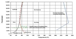
Normal operating condition and shut-in condition are also shown for a single 8-in. nominal flowline with UOD-value of 0.6 BTU/ft2 hr °F, giving more than 12 hours cooldown time for early life production. The wellhead was located under 5,000-ft water depth, where the ambient seawater temperature was below 40 °F. For this case, the normal operating conditions lie out of the hydrate and wax formation regions due to the high wellhead temperature. However, for low flowing wellhead temperature and shut-in conditions, the pipeline system could lie in the hydrate and wax formation regions.
To avoid the risks of hydrate formation and wax deposition, the fluid temperature should be maintained above the hydrate and wax formation temperatures. Also, the subsea system should be designed to provide adequate cooldown time for shut-in and restart operations. Therefore, both steady state and transient conditions should be properly accounted for the subsea system designs.
A daunting challenge that operators face in developing deepwater subsea fields is putting together a cost-effective solution for managing hydrate blockages and wax deposition. The effective preservation of fluid heat in a pipeline system is one of the most important design parameters for preventing such solid formations. These flow assurance risks can be managed through effective system design, such as thermal insulation, high grade materials, and sophisticated mitigation systems which would normally increase the capital cost. Also, they can be managed through operations like extensive chemical inhibition, pigging, and flow monitoring. These actions will drive up the operating cost.
Chemical solutions that focus on total prevention and/or abating hydrate and wax issues are taken into account in the umbilical design, tree selection, subsea hardware, and topsides engineering. Chemical injection lines, and subsequently the umbilical cross-section, must be sized to inject the appropriate amounts of inhibitors. The topsides must be equipped with pumps and tank storage large enough to deliver chemicals to the subsea chemical injection locations. Depending on the fluid chemistry issues present, the subsea tree must come equipped with enough injection ports to deliver chemicals to locations at the tree and downhole. Additionally, subsea hardware is typically equipped with hot-stabs for subsea intervention should a hydrate plug arise. All are examples of how chemical solutions to wax and hydrate prevention can affect a project's capex.
Thermal insulation provides hydrate and wax controls by maintaining fluid temperature above hydrate and wax formation conditions. It also provides enough cooldown time for shutdown and restart operations, or to prepare for long-term shutdown. Non-chemical flow assurance solutions such as pipe insulation and heating are often used for thermal management of subsea pipeline systems to alleviate the steep opex costs incurred from chemical solutions. In certain instances, non-chemical solutions can reduce capex as well.
Non-chemical solutions
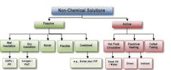
Non-chemical flow assurance solutions for hydrate and wax management can be partitioned into two types: passive system and active system. Both solutions are discussed below.
Passive systems
Passive systems do not require an input of energy such as work or heat to be effective. Heat retention is achieved by surrounding the flowpath with materials that offer a high resistance to heat transfer with low thermal conductivity. Examples of thermal insulation system are wet insulation, dry (pipe-in-pipe) insulation and pipeline burial. Flexible pipes can be insulated as well, although the outside diameter of flexible pipe is intrinsically large and limits the amount of insulation that can be applied. A combination of pipeline wet insulation, burial, and trenching can provide a cost-effective passive system. Costs for passive insulation systems are generally figured into capex only. The insulation system can impact on-bottom stability, cost of installation, and field joints design. Riser insulation may impact fatigue. The insulation material must withstand hydrostatic pressure imposed in deepwater. Other concerns may include water ingress, creep, and thermal aging.
Wet insulation
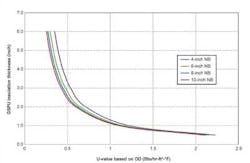
Wet insulation refers to all types that can be molded to the outer surface of a pipeline or equipment and, when submerged, do not require a protective barrier. The insulation is directly exposed to seawater and water may diffuse into the insulation. Wet insulation is typically tailored to withstand compression due to hydrostatic head in deepwater. This insulation may be solid polymers such as polypropylene (PP) or syntactic foams such as glass syntactic polyurethane (GSPU). The critical parameters for the design are thermal conductivity, insulation thickness and specific heat capacity along with density. Other insulation requirements are flexibility, toughness for handling and application limits. The U-value of pipe is generally used to optimize the performance requirement of a system. The thermal performance is better when the U-value is lower. PP and GSPU offer good mechanical properties along with an extended track record in the offshore oil and gas industry.
Polypropylene has been used as a coating material for corrosion protection and/or thermal insulation for the past several years. PP resists water permeation and can be used for high temperature applications up to 310°F (155°C) and water depth to over 9,800 ft. However, PP has limited flexibility and is primarily limited to field joint and pipeline (pipeline, riser, and jumper) insulations. Chevron's Blind Faith project in 7,000 ft water depth (GoM) is one of the examples of a high temperature, high pressure field application of PP used as insulation to mitigate flow assurance issues.
GSPU offers the advantage of being easily molded and flexible, and can be applied to pipelines in addition to field joints and subsea hardware. GSPU can be applied in water depths near to 10,000 ft and temperatures as high as 240°F (115°C). Many product lines of GSPU have flexibility with respect to installation and can be installed using all subsea laying methods, notably reeling, J-lay, and S-lay. For example, flowlines for Shell's Perdido project were insulated with Perma-Pipe's Auto-Therm GSPU. An insulation thickness of 3-in. GSPU was applied over roughly 80,000 ft of 10-in. NB pipe in 9,600 ft water depth.
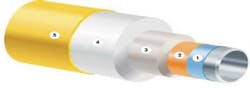
Dry insulation
In many deepwater applications, a desirable U-value for the pipeline system cannot be achieved with wet insulation. When a low U-value (typically below 0.44 BTU/ ft² hr °F) is required to maintain fluid temperature at a predetermined safety margin above hydrate formation or wax appearance temperatures during normal operation, pipe-in-pipe (PIP) insulation can offer significant reductions to both material and installation costs. For a typical PIP configuration, the inner (carrier) pipe is insulated with a low conductivity dry insulation such as an aerogel or low density polyurethane foam. The outer pipe is typically steel but in shallow water instances can be polyethylene. For many deepwater applications requiring a rigid outer pipe, an air gap exists between the outside diameter surface of the insulation and the inside diameter of the outer pipe. The effective conductivity of the air gap is of reasonably low value and also adds to the heat resistance of the system.
For an example, a PIP insulation configuration was used to achieve a low U-value for the Cascade-Chinook development in Walker Ridge block 425 in the GoM. A 9-in. X 14-in. PIP insulated pipeline approximately 39 km (24 mi) in length was installed successfully in 8,250 ft of water. To achieve a required U-value of 0.22 BTU/ft² hr °F, 16 mm of Cabot's Nanogel aerogel was applied.
Another example of a deepwater PIP system is the Canupa field located east of the state of Espirito Santo in southeast Brazil. Production gas is transported via 20 km (12 mi) PIP insulated pipeline to an FPSO located in the Golfinho field. The PIP design consists of an 8-in. inner pipe insulated with Aspen Aerogel insulation panels and a non-standard 13-in. outer pipe to achieve a target U-value of 0.14 BTU/ft² hr °F.
Buried pipeline
In addition to providing on-bottom stability and protection from dropped objects, buried (or trenched) pipelines enhance thermal insulation. Burial depths of 1 to 3 meters are common. The large surrounding layer of soil coupled with high heat capacity can significantly improve a pipeline's cooldown time upon shut-in. Burial can be combined with any one of the other passive insulation systems (for example, 3-in. wet insulation plus 1 m pipeline burial).
One such example of pipeline trenching solely as a solution to flow assurance issues is Shell's Coulomb project. The Coulomb subsea gas/condensate field is located in the GoM in approximately 7,500-ft waters. It was installed in 2004 and consisted of a 27-mi, bare 8-in. pipeline tie-back to Na Kika platform. Due to waxing issues after production start-up, the pipeline was trenched 6 to 8 ft in June 2006.
Flexible pipe
Insulation material typically used for flexible pipelines is thermoplastic syntactic polypropylene material in the form of multilayer tapes applied in between the tensile armour layer and the outer sheath. A new type of syntactic polypropylene insulation material for deepwater flexible pipe was recently tested and verified for use in water depths down to 6,562 ft.
Combined methods
Another option for a passive insulation system is to combine wet or PIP insulation with trenching and burial of the pipeline with a flexible or wet insulated riser. The burial of insulated pipeline improves the pipeline thermal performance by lowering U-value of the system and by adding thermal mass to it, increasing heat retention. Flow assurance analyses conducted in the concept and FEED stages of a project combined with cost estimates for capex and opex determines technical and cost-effective solutions for a deepwater development.
Active systems
Active systems require input of energy in the form of work or heat. Hot fluid circulation, electrical heating, coiled tubing remediation and bundled pipelines are examples of active systems. Hot fluid circulation requires heat to elevate the temperature of the circulating fluid and work to pump the fluid through the pipeline. Similarly, direct or indirect electric heating requires energy in the form of electric current to supply heat to a pipewall. Thus, the costs for active systems affect both capex and opex, although the opex for active systems can be offset by the savings in operating costs. Using active heating, hydrate plugs can be remediated safely and effectively by evenly applying heating to a pipeline. Blockages can be remediated in hours whereas depressurization alone can take days or weeks.
Hot fluid circulation
Hot fluid circulation involves heating the production fluid or pipeline by means of circulating hot fluid either in a bundle or through dual flowlines and risers. If the flowline system is a pipe bundle, fluid is circulated through small tubes which transfer heat to the production carrier pipe by means of conduction. The circulation fluid can be either diesel or water depending on availability. If the system is a dual pipeline configuration, hot dead oil can be circulated through the pipelines until the pipeline is warmed above hydrate conditions. This is typically done prior to a cold restart. Hot oil circulation is a proven technique which is widely used in deepwater tiebacks.
For example, hydrate plugs formed above the mudline in two dry tree oil wells in the GoM. These were discovered when crews tried to open the downhole safety valve with crude to return the wells to production after they were shut down due to hurricane evacuation. Chemical injection attempts failed to melt the hydrate blockages. Finally, hot oil was injected into the tubing-casing annulus with about 1 bbl/min injection rate and 150 °F injection temperature. The pressure/temperature condition inside the tubing located 3,000 ft below the sea level came out of the hydrate formation region within four hours. Hydrate plugs in two dry tree wells melted after 6 and 60 hours of injection time.
Electrical heating
Electrical heating is currently being used for hydrate and wax formation prevention on pipelines and risers during shut-in periods subjected to technical and economical viability. Direct electric heating is achieved by passing an electric current directly through the walls of the subsea pipeline and/or riser. The energy dissipated in the pipe wall due to resistance to the electric current is transferred as heat. Indirect heating, as an alternative, is accomplished by installing a heating element on the carrier pipe outer surface, transferring heat to the carrier pipe via thermal conduction.
One particularly interesting deepwater project that involves DEH is Shell's Na Kika project, offshore GoM in water depths ranging from 5,800 to 7,000 ft. This particular field consists of 25-mi daisy chain flowloop with six PIP insulated 10-in. x 16-in. flowline segments ranging from approximately 1 to 8 miles in length. A center-fed DEH concept was applied as a hydrate remediation strategy. The six flowline segments were equipped with an integral electrical heating ready (EHR) connection point at the mid-line electrical connection assembly located at the pipeline geometric center on the seabed. Through the connection, power could be delivered continuously to the flowline over several days in the event of hydrate blockage.
Coiled tubing
Coiled tubing is primarily used to remediate hydrate blockage. Tubing is run into a pipeline, typically from the host or workover vessel, in an attempt to deliver inhibitor to the hydrate plug, jet out the plug, or drill through the plug. The decision whether or not to have coiled tubing access must be made during the design stages of the project, considering safety and operation issues. Tubing is inserted through a lubricator usually at platform or floating workover vessel in an effort to get an inhibitor such as glycol to the face of the plug. Tubing walls are porous to allow air/gas to lubricate the tubing travel for greater penetration. Coiled tubing has been applied to hydrate remediation as far as 15,000 ft operations.
Conclusions
Recent advances in non-chemical flow assurance solutions and technologies can be applied to develop thermal management for the mitigation of hydrate and wax problems for deepwater field developments. For example, PIP insulation combined with electrical heating can help prevent and remediate these solid depositions and minimize capex/opex by avoiding the use of chemical inhibitors, minimizing pigging frequency, and avoiding dual pipelines. Because of operational flexibility and high efficiency, thermal mechanisms can effectively manage hydrate and wax formations in deepwater oil and gas field development throughout the production operations of field life.
The Authors
Mark Chapman is senior flow assurance engineer at McDermott Subsea Engineering, McDermott, Houston, Texas.
Keshawa Shukla, Ph.D, is flow assurance manager and global subject matter expert at McDermott Subsea Engineering, McDermott, Houston, Texas.
Offshore Articles Archives
View Oil and Gas Articles on PennEnergy.com