Alloy annular plugs effective for casing annular gas flow remediation
Sustained casing pressure (SCP) is a growing problem among offshore wells, leading to expensive shut-ins and remediations on many wells. Poor primary cementing, inadequate cement coverage, gas/water influx during or after cement placement, mud-cake shrinkage, and the development of stress-induced microfractures and microannuli are all cited as potential factors in SCP. The time between well completion and the onset of SCP can indicate the more likely causes.
While there are several suspected culprits for SCP, pressure and temperature cycles are high on the list. Casing growth and contraction that result from production cycles and stimulation operations can decouple the bond between the cement and casing. These forces can also stress-crack the cement. Both scenarios can create small pathways for high-pressure, low-volume communication of annular gas to the surface, but the inaccessible nature of these pathways limits remediation options. Early onset mechanisms can include:
- Gas-cutting of the cement
- Gas movement through a free-water channel
- Casing/tubing connection leaks
- Inadequate cement coverage.
Late onset sustained casing pressure can result from:
- Channels of bypassed mud
- Stress cracks in the annular cement sheath
- Shrinking or drying of the mud filter-cake
- Casing/tubing connection leaks.
These factors are well documented, appearing frequently in past research. The following sections summarize a few of the main causes.
Gas migration
A common factor in annulus gas pressure is gas migration. Gas migration, annular gas flow, and gas leakage are terms that describe gas entry into a cemented casing or borehole annulus. Often, gas enters the cemented casing or annulus even though the initial hydrostatic pressure of the cement column is higher than the gas-zone pressure.
This leakage occurs when hydrostatic pressure is lost before the slurry has achieved enough static gel strength to resist gas flow through the cement. The hydrostatic pressure exerted by a cement slurry in the wellbore should be able to maintain an overbalance pressure on the gas-bearing formation and prevent gas from percolating or channeling through the fluid column. Unfortunately, most cement slurries, unless they are specifically designed to control gas, do not retain the capability to transmit full hydrostatic pressure in a static condition.
The most widely accepted cause for annular gas migration is the incapability of the cement column to maintain an overbalance during transition time (the time required for the slurry to change from a fluid to a solid), combined with volume reductions resulting from fluid loss. Recent research suggests that foamed cement is becoming a viable option for controlling gas migration.
Poor mud displacement
Gas pressure in the annulus can also become a problem if long-term mud displacement is poor. A primary requisite for lowering gas pressure is effective mud displacement, which can provide a relatively clean pipe and formation surface to which the cement slurry can bond. Generally, 90% displacement efficiency provides adequate zonal isolation, while 95% provides excellent zonal isolation.
Lowering the drilled-solids content of the drilling mud, conditioning the hole, and reducing the long-term gel strength of the cement can help obtain more efficient mud displacement. Foamed slurries also help reduce migration by displacing drilling mud better than nonfoamed slurries. However, using foamed cement does not eliminate the need for proper mud conditioning or for following best cementing practices. When foamed slurries are mixed outside of the optimal range of foam quality, they are less capable of improving displacement effectiveness and zonal isolation.
Cement sheath cracking
Another cause of annular gas pressure is cracking of the cement sheath. The failure of well sealants is largely the result of their in-situ stress condition. Changes in stress level in the sealant mainly arise from either an increase or decrease of pressure or temperature during the operation of the well (production, injection, depletion, subsidence, and stimulation). If in-situ compressive stresses are present in the sealant, it is more likely to fail in shear. In general, if Young's modulus of the sealant is higher than that of the rock, it is likely to fail from tensile cracking when the pressure or temperature inside the casing increases.
Because the compressive strength of a sealant, which is traditionally used as a quality indicator, is not sufficient to determine which sealant is most suitable for the effective zonal isolation of a well, other mechanical properties are required. These properties include Young's modulus, Poisson's ratio, tensile strength, shear strength, and bonding strength. Careful evaluation of these properties could result in more efficient sealant design, helping to reduce gas pressure in the annulus.
Operators need a simple way to maintain production in wells threatened by annular gas pressure. Until recently, researchers had not concentrated on an economical, simple way to repair these wells. However, the results of recent large-scale testing suggest that alloy-metal annular plugs can have a significant impact on the industry by reducing sustained casing pressure (SCP).
SCP remediation
The following options have been used in the past as possible remediation solutions. However, these solutions met with limited success because of the following difficulties:
- Distance between point of injection, which is usually the wellhead, and gas source
- Inaccessibility to wellhead piping
- Mud contamination of fluids during installation of heavy-weight brines.
Current technology can control, but does not eliminate SCP, requiring a continuous monitoring and pressure-maintenance program. These programs should be maintained over the life of the well, which requires time and expensive manpower resources.
Remediation alternative
A proposed solution that shows promise for eliminating the shortcomings of the previously cited solutions is the use of pelletized alloy-metals. This solution involves placing pelletized alloy-metal into the well's annulus, heating the alloy-metal above its melting point, and then allowing the alloy-metal to cool.
When the alloy-metal cools, it expands slightly, to help enhance the annular seal. This method has shown promise on small-scale physical models. The following is an evaluation in the full-scale pipe-in-pipe and pipe-in-sandstone geometry of the alloy-metal solution.
A large-scale testing apparatus was developed jointly by Halliburton and Texaco to duplicate the installation and formation and to test the integrity of an alloy-metal annular seal. This technology was developed to remediate wells that have sustained annular casing pressure, and a patent is pending on the concept. Before attempting field trials with the alloy-metal, researchers ran tests to determine two items:
- Integrity of annular seals in typical field annular geometry in pipe-in-pipe and pipe-in-sandstone environments
- Means to locate the preformed alloy metal in an annular configuration - not currently available.
The proposed alloy-metal solution meets expectations on small-scale physical models. Large-scale testing will help provide data and insight in full-scale geometry models, and the information gathered in this testing will help introduce this technology in the field. If the tests are successful, alloy-metal annular plugs could save the industry millions of dollars in remediation costs and possibly solve the SCP problems found on wells globally.
Method and scope
The objective was to test the proposed alloy-metal formulation for pressure integrity in a field geometry. The tests were completed within the following conditions:
- Model length limited to 15 ft, and deviated at 30 degrees from vertical
- Alloy-metal pellets placed and activated with water-based drilling fluid present in annuli
- Temperature limited to 200°F
- Plug long-term integrity tested by pressure-cycling the inner casing.
Models included pipe collars in the lengths of the pipes to enhance the sealing ability of the cooled alloy-metal. The plug lengths in actual wells will need to be 45-60 ft in length, to ensure that collars will be covered by the alloy-metal, resulting in a more efficient annular seal.
Execution
Two large-scale models were constructed on common field geometry:
- Plug test No. 1: 5 1/2-in. by 8 1/2-in. pipe-in-sandstone
- Plug test No. 2: 10 3/4-in. by 13 3/8-in. pipe-in-pipe.
The models were constructed so that gas could be subjected to the bottom of the formed alloy-plug. The final alloy-plug creation was limited to 5 ft or less. To enhance the gas seal of the plug, simulated casing collars were constructed on the inner pipes.
Adjacent to the inner-casing collar, a small recessed portion of the outside casing was made in the three pipe-in-pipe models and an 8-in. washout was made in the pipe-in-core model. The washout section simulated a thin shale section where the alloy-metal could seal the upper and lower permeability of the core model. Plugs were placed and formed with the models in a 30 degrees-from-vertical angle. Alloy pellets were deposited through 12-lb/gal water-based drilling mud.
After the continuous plug was formed, a gas pressure of 100 psi was applied to the bottom section of the model. The annulus above the plug was monitored for gas communication. Models were dissected to expose the alloy plugs. If the plug maintained a pressure seal, the model was saved for the identification of plug.
Plug test No. 1
After the alloy-metal plug was formed across the collar and washout section, gas pressure was applied to the sand pack below the metal plug. The seal held the gas flow for 15 minutes; then a small volume of gas in the form of bubbles was seen at the top of the 15-ft model. The rate of the gas leak was about 5 cu cm/min.
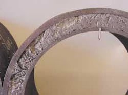
Even though the seal held for 15 minutes, the plug was considered a partial failure and the model was dissected to determine the cause of the leak. Upon exposure of the formed alloy-metal plug, it was found that an incomplete melt of the metal segments had occurred. Only 2 1/2 ft of the planned 5 ft had melted to form the annular seal. It is thought that the shortened plug was the main reason for an early seal and the small leak rate. This learning was carried over into test No. 2 in the form of ensuring that the entire pelletized metal section was heated to at least 185°F.
Plug test No. 2
Based on the results of test 1, the inner pipe temperature was periodically logged from the bottom to the top of the pipe. Heat remained on the model until a temperature greater than 185° F was measured above and below the alloy-metal plug. This procedure helped ensure that all the alloy-metal pellets melted. Then, once cooled, the alloy-metal would form the highest possible plug integrity.
After cooling the model to room temperature, the bottom of the model was tested for possible gas leakage. After applying 100-psi gas pressure to the bottom of the model for one hour, it was determined that the plug had formed a gas tight seal.
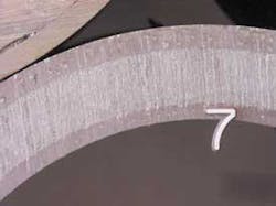
Upon dissection of the model, it was found that the alloy-metal had impregnated most of the 20/40-mesh sand pack, except for the very bottom and a section about 4 ft from the bottom of the model. Shear bond of the metal impregnated sand indicated that the alloy-metal/sand mixture had intimate contact with the outer and inner casing.
This finding indicates that in field application of the alloy-metal technology, the melting of the pellets should be localized to the main portion of the proposed plug. A possible solution to control downward flow of the melted alloy could be the installation of a higher melt alloy with an incomplete melt, then a lower-melt alloy above the first plug. This solution could provide an annular barrier for the second plug to rest above, which should form the gas tight seal.
As evident from both of the tests, the upper part of the plug becomes marbled with the wellbore fluid. However, if there is sufficient annular length and melt of the pellets, the density differences between the alloy-metal and annular fluid should remove the drilling fluid from the final alloy-metal seal.
Thus far, testing has proved the concept, in a large-scale environment, that the alloy-metal pellets could be placed in an annulus through mud. The length of plug will affect the final seal. Adequate heat should be applied to help ensure that all of the installed material (alloy-metal pellets) is melted.
Researchers have planned further testing that could clarify the limits of the technology. The alloy seems to be a viable possibility for sealing the annulus if a proper support barrier can be formed below the pelletized alloy-metal. Further testing is necessary to fully explore the possibilities.
Acknowledgement
Texaco Oil Company and Halliburton Energy Services Inc. managements provided support for this article.


