DEEPWATER OPERATIONS: Flowline insulation with heat storage increasing cool-down time
Thermal insulation of offshore flowlines is often the best way to keep crude in flow conditions, or to avoid formation of hydrates or waxes and asphaltene deposits for as long as possible. With deepwater fields, these concerns are particularly critical due to the risk of production shutdown.
Bouygues Offshore and IFP have developed a new thermal insulation concept, named ILS, based on the use of liquid/solid phase change materials (PCM) that are specifically formulated for the needs of the ILS program. In normal flowing conditions, the PCM liquefied by the oil's heat flux acts as a heat accumulator.
During production shutdowns and the resultant cool-down period, the crystallization of the phase change material partially restores this stored heat to the flowline. Therefore, such an insulated coating induces a significant thermal inertia in the flowline, and the cool-down delay before hydrates formation is 2-4 times longer than with existing insulation technologies.
Due to the incompressibility, the low density and the low cost of chosen phase change materials, ILS can meet deepwater and ultra-deepwater flow assurance requirements as well as competing with existing pipe-in-pipe or syntactic thermal insulation concepts.
Development program
Leading actors involved in the ILS technology development are Bouygues Offshore, for technical requirements, basic design, and marketing, and Institut Francais du Petrole (IFP), for basic research on PCM materials and ILS formulations and their qualification program, and various industrial partners for ILS materials formulation and fabrication. The main development phases have been:
- Technical assessment and modeling of ILS thermodynamics
- ILS flowline design (single flowlines and bundles) and ILS risers
- ILS materials formulation and lab tests
- Qualification program on ILS materials and on detailed designs, including aging tests and thermal tests under hydrostatic pressure.
Material selection
Several criteria were applied in the search for a phase change material (PCM) suitable for thermal insulation for deepsea pipelines. The selected PCM had to be or have:
- Without gas, and therefore incompressible, which means no depth limitation
- With thermal conductivity similar to other solutions for deepsea applications (l = 0.12 to 0.17 W/m.K)
- Allow no convection in both phases - solid or amorphous
- High thermal stability
- With a phase transition temperature 5° C or 10° C above the hydrate formation temperature
- High latent heat of transformation
- Reliable reversibility
- Available in large scale at low cost.
On the basis of known phase change materials, an adequate material was formulated to respond to all the selection criteria. This material is solid (crystallized) at cold temperature and amorphous above its crystallization temperature. In the amorphous state, the selected ILS does not flow.
Working cycle
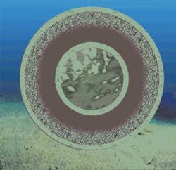
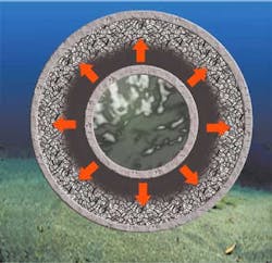
During steady state production (see figure) a fixed thermal gradient is established inside the insulation layer between the hot effluent temperature and cold water. The ILS material comprised between the casing and the transition temperature (Tr) isotherm remains in its crystallized phase, and the other part of the material comprised between the Tr and the pipe becomes amorphous. So a layer storing crystallization latent heat is developed around the pipe in continuous production conditions.
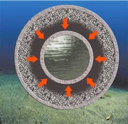
During shutdown occurrences (see figure), the core of the flowline does not receive any more thermal flux from the effluents, necessary to offset thermal losses through the insulation layer. The effluents, steel pipe, and insulation layer itself all initiate a cool-down phase, that tends to move the Tr isotherm towards the flowline center, as shown by the arrows on the figure. So the ILS material crystallizes in concentric layers, but the crystallization front motion is strongly slowed down by the released latent heat. Meanwhile, the heat stored in effluents and pipe steel diffuses into the amorphous phase until their temperature reaches Tr.
In practical terms, effluents and pipe are maintained at the transition temperature Tr as long as an amorphous phase remains in the ILS insulation. Given a hydrate formation temperature, we have the possibility of choosing or formulating the proper ILS material with a greater transition temperature.
During production re-start (see figure), the flowline core is again heated by the production flow, and the flowline tends to recover slowly its steady state temperature gradient and its initial heat storage. The resulting over-cooling of effluents is very low and appears only when production is warm enough to develop a thermal gradient into the amorphous phase, far away from hydrate formation temperature. The energy is therefore stored very gradually, when the oil temperature is not critical, and released in shutdown conditions, when the oil temperature could be a real issue.
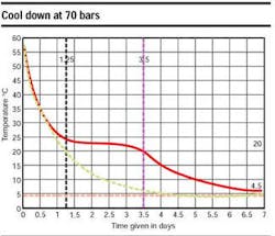
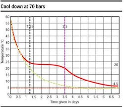
The superposition of the two curves (same characteristics - with and without the latent heat effect) in an accompanying graph highlights the latent heat effect, which increases the cool down time by a factor of three. The pipeline figure shows the pipe temperature evolution (°C) versus time (hours), in shutdown condition, at 135 bars, 4°C. Here, the correlation between calculation and measurements is excellent.
The purpose of the tests is to assess the mechanical and thermal properties of the selected ILS during the production and the shut-down phases and its behavior during thermal aging. The following tests have been performed: thermal conductivity, thermal stability, measurement of transition latent heat, reversibility of the heat release phenomenon, and influence of pressure.
All the tests were performed in laboratory conditions on material samples. In order to verify their validity in deepsea service, a thermal test was performed on a flowline scale model, immersed in water at 4°C at 150 bars.
Editor's Note: This is a summary of a technical paper to be presented at the Deep Offshore Technology Conference in Rio de Janeiro, Brazil in October 17-19, 2001.
