Paul Ellerton, Andrew McIntyre - Prospect UK
Understanding and managing flow and thermal fields is becoming more important as the oil and gas industry strives to understand and minimize risks caused by corrosion and hydrate formation. Computational fluid dynamic (CFD) analysis helps to understand the problems, minimize risks, and tackle issues early in the design process, since prevention is infinitely preferable to cure.
Many offshore and subsea pipelines and process systems have associated integrity and flow-related risks. Corrosion and blockages – arising, for example, from formation of hydrates and waxes – all increase project risk and operational costs by impacting process efficiency and production rates.
What determines whether an unwanted or adverse chemical or thermal process is going to take place within your system? How do you better understand the risks involved? Most importantly, how do you reduce the risks?
The chemical or process environments (chemical composition coupled with system environment) govern the potential for such events and control the rate at which they progress. While this can be managed by adding the right chemicals at the appropriate rate, the flowfield and thermal conditions can be significant factors. Understanding the flow, pressure, and thermal mechanisms within such systems can help prevent problems, minimize operational risks, and reduce rectification costs related to equipment and chemicals.
Corrosion can be a significant issue if susceptible material components are subjected to particular fluids under specific flow and thermal environments. Computational fluid dynamic (CFD) analysis can be used to determine if, and for how long, vulnerable materials are subject to such conditions. CFD is an engineering analysis tool which can solve flow-related or thermal scenarios in what is analogous to a “virtual test facility.” The key skill is in how to use this tool to help deliver a design or process solution.
CFD offers insight into the mechanisms composing operational risks and helps identify ways to reduce these risks. By understanding the flow mechanics required to cause a potential (or known) corrosion risk, mitigation techniques can be investigated and an engineering answer obtained.
For instance, with CFD all of the potential variables can be explored and the position and flow rate of a required chemical can be optimized. This in turn reduces the risk to system integrity and offers a means to limit the chemicals required.
One field example of CFD use is the optimization of a chemical inhibitor to reduce the corrosion risk. A chemical inhibitor can be injected into a process fluid with the aim of coating the inside of the process equipment, at a concentration required to minimize corrosion risk. The position of the injection, its flow rate, and the mixing processes all are critical in this equation.
In one case, the inhibitor injection quill position in a section of pipework, had to be optimized so that mixing of the inhibitor with the process fluid occurred quickly, prior to reaching process-critical equipment. The process was a multiphase mixture of liquids and gases with the inhibitor injected as a liquid.
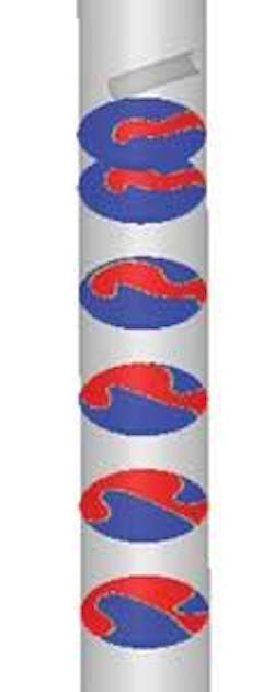
The analysis employed multiphase modeling to determine the efficiency of the mixing and the concentration of the inhibitor throughout the process system. The quill was positioned at several locations within the piping and the inhibitor released into the multiphase flow to determine the optimum position. One such flow field and mixing analysis for a given quill position is shown in Figure 2. The quill was positioned on a straight stretch of pipe, the process fluid shown in blue and the inhibitor in red. The injected inhibitor formed an annulus, coating the pipe as it moved downstream.
The analysis found that when positioning the quill, pipe geometry was important. The quill was less effective when positioned on the inside immediately downstream of a 90° elbow due to the poorly distributed flow past the inhibitor opening. A large length of pipe was required to fully mix the fluids, although mixing was promoted with the addition of bends downstream from the injection point. If the inhibitor is injected with negligible momentum, it follows the flow within the wake of the quill. This investigation helped understand the flow mechanisms required to prevent corrosion and where to position a quill to minimize the risk.
Model fluid behavior
Computational analysis can model fluid behavior explicitly and allows for forced and free flowing convection which facilitates thermal effects modeling. In ensuring efficient subsea production, a subsea production system (SPS) must be free of blockages caused by such adverse formations as hydrates. During system production this can be achieved through insulation and chemical inhibition. However, in the event of a shutdown the production fluids ideally must remain above the hydrate formation temperature for however long it takes the operator to resolve the situation.
Hydrates formation is a function of temperature and pressure, and in a shutdown, system cold spots provide a major risk of build-up. Tools such as CFD determine whether the hydrate formation temperature will be reached and to design insulation systems to reduce this risk.
During production, the fluid bore and surrounding fluid deadlegs remain warm and in most parts there are large amounts of replenishment of the fluid. A shutdown cuts off replenishment so cooling takes place due to the low temperature of seawater surrounding the system. Fluid in the production bore must be kept above the hydrate formation temperature for the entire assessment period before production is re-started or else more significant action is required. During cooldown, the only fluid movement is due to convection which is insufficient to prevent hydrate formation.
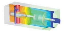
CFD analysis has been used to predict fluid temperatures in the system during production and cooldown (of the order of 10 hours). Figure 1 shows temperature contours in a subsea production valve after 10 hours of cooldown. Here the warm production fluid (orange) will be safe from hydrate formation while the cold spots (blue) can cause a problem.
Areas cold enough for hydrate formation have to be insulated to retain warm production temperatures. System purging can also mitigate hydrate formation.
Following the initial SPS analysis, insulation was applied and the valve and the simulation re-run to confirm that a hydrate-forming thermal environment was avoided. This analysis saved time and money because full-scale testing of different SPS configurations was not required. It also gave insight into equipment that is impossible otherwise.
