Planned, unplanned subsea interventions prevent production shut-in
Avoiding costs and risks of abandoning flowing well in Petronella field
Gordon Mackenzie, Graeme Kelbie, Baker Oil Tools
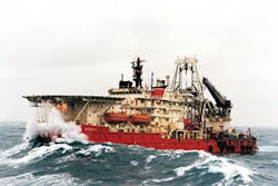
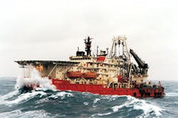
As the number of subsea tiebacks and intervention operations in the UK sector of the North Sea has grown, so has the trend to conduct the intervention operations from fit-for-purpose subsea intervention vessels.
The support capabilities of these vessels - i.e., saturation and shallow diving, heavy lifting, subsea construction, well servicing, workover, temporary and permanent abandonment, fire fighting, helicopter service and remotely operated vehicle (ROV) operations - make them ideal for subsea intervention service. However, their deck and below-deck area make pre-planning, including selection of equipment to have onboard, critical.
The foresight of an operator in planning and communicating with all involved for an intervention operation in the Petronella field resulted not only in the success of the planned intervention, but also in the ability to conduct a successful unplanned intervention to provide temporary wellbore isolation that avoided potential costs and risks.
Planned water shut-off
The operator’s planned intervention involved removing scale and shutting off water in an artificial lift well and then re-configuring the gas lift system to enhance oil production. Well production figures indicated an unacceptably high increase in water cut. Additionally, the operator discovered barium sulphate and calcium carbonate scale buildup in the tubing, which created wellbore completion restrictions of unknown geometry.
The operator’s objectives of the intervention were to remove calcium carbonate scale, carry out water shutoff isolation, and finally re-configure the gas lift system. The operator completed the well with 4.50-in., 13.50 lb/ft tubing above a 7.00-in., 29 lb/ft liner. Bottomhole pressure was 3,059 psi with a temperature of 163°F at an isolation depth of 7,455 ft. The wellbore fluid was a mix of 35° API oil and produced water. There was a known crossflow condition between the zones to be isolated of 200 b/d from the lower to the upper zone.
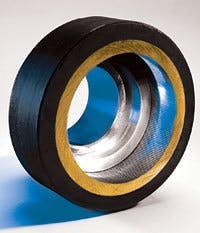
Normally, nipple size is used to determine plug size when isolating zones for water shutoff. However, in this well, scale deposition had reduced the restrictions of all IDs, so there was no way of knowing the actual minimum ID of the completion above the liner. The operator chose to use inflatable bridge plugs for the water shutoff isolation based on their high expansion characteristics. The operator mobilized both 3.00-in. OD and 2.13-in. OD inflatable bridge plugs because of restriction uncertainty.
Both systems were configured to be immune from the effects of the recorded crossflow when deployed via electric wireline. Additionally, the operator used only the 3-in. plug to provide an effective seal and anchor within the 6.184-in. ID of the 7.00-in. liner. The operator also chose to use a fluid reservoir carrying system as part of the inflatable package in an effort to guarantee the quality of the inflation fluid with which the bridge plug would be actuated.
The operator treated the well with hydrochloric acid to remove as much of the calcium carbonate scale as possible. In total, the operator conducted 11 acid treatments by pumping between 210 gal and 630 gal of acid from surface through the tree via a TR 12 hose. While the acid was being displaced into the tubing, a 2.29-in. OD slickline drift was used in an attempt to agitate the acid and increase the effectiveness of the acid operation.
After the 11 acid treatments, the operator ran a 3.10-in. OD wireline drift to confirm that the 3.00-in. OD inflatable bridge plug could be deployed to the required setting depth. The preference to run the larger-OD bridge plug was dictated by the available riser length of 59 ft. Had the 2.125-in. plug been required, it would not have been possible to use the reservoir fluid carrying system because of the increased length necessary to transport the 4.95 gal of required inflation fluid.
With this access now gained to the wellbore, the service provider deployed the 3.00-in. bridge plug complete with 2.875-in. OD reservoir carrying system containing 4.29 gal of fluid to the setting depth of 7,453 ft via conventional 7/32-in. mono-conductor electric wireline. The inflatable bridge plug was deployed and set as per the predetermined procedures.
After the bridge plug was set, a 24-hour well test was conducted to ensure the integrity of the isolation. Subsequently, the operator conducted two dump bailer runs of cement via electric wireline to ensure the longevity of the permanent lower-zone subsea abandonment. Attempts were then made to reconfigure the gas lift system. However, location of the gas lift mandrels with traditional slickline tools proved impossible, possibly because of some scale deposition that was not removed by the pre-isolation acid treatments.
The operator, although unable to reconfigure the gas lift system in this well, proved by the evidence supplied from pre- and post-acid treatment caliper logs that significant quantities of scale were removed from the wellbore. The operator’s overall objective of the subsea intervention/lower zone abandonment was met as indicated from both the increased level of post-isolation oil production and the reduced level of unwanted water production.
Unplanned inflatable isolation
During the same subsea campaign, the operator needed to install a subsea isolation plug in a water injection well to repair leaking subsea tree valves and a ruptured injection line from the platform. The operator’s objectives were to install a deep-set pump-open plug on wireline, install a seal receptacle below the hanger, insert a tree valve isolation tool (TVIT) and finally repair the leaking flow wing valves and isolate the well.
While performing the initial survey to determine the tubing condition, it was learned that the tubing had parted above the subsurface safety valve (SSSV), creating a gap of some 32 ft. This situation rendered the original well entry program inoperable. However, some quick thinking from both the operator and the service provider enabled a revised program to provide temporary wellbore isolation by using the onboard availability of through-tubing inflatable tools from the earlier intervention operation.
The operator’s plan was to run a 3.00-in. OD through-tubing inflatable crossflow retrievable bridge plug into the 9 5/8-in., 47 lb/ft casing between the sections of parted tubing to control the well and allow the flow wing valves to be repaired. The service provider’s rig-up height restriction due to the vessel system restriction precluded running a fluid reservoir system, so a standard electric wireline running assembly was run in hole to a depth of 617 ft mid-element.
After 6 hrs of pumping, it was evident that the operation was not performing to specification. After the operator recovered the bottomhole assembly (BHA) to surface, it became evident that the filters on the setting tool were plugged by what was later confirmed to be iron sulphides. This wellbore-borne debris prevented the tool from functioning correctly.
The service provider made up a second BHA and ran with clean fluid pumped from surface to help prevent a recurrence of the problems encountered during the first run. After the service provider pumped for 7 hrs, there was no indication that the plug had contacted the casing wall, so the decision was made to stop and pull the assembly to surface. Again, the filter section of the system was plugged with iron sulphides.
Further discussions between the service provider and the operator led to a decision to deploy a fluid reservoir system as in an open hole situation. A full risk assessment was carried out to identify any risk while deploying the BHA into the well. The operator made up and ran the new assembly in the hole to a depth of 618 ft mid-element. The service provider pumped for 2 hrs 35 min, which was 7 min earlier than the predicted time and a good indication of a set was seen. The operator recovered the BHA to the surface.
The service provider performed a pressure test across the bridge plug after the BHA had been recovered indicating that well flow had not stopped. The plug was recovered with slickline. Indentations along its element indicated that it had been set across the severed control line, allowing bypass across the plug.
Both parties discussed how to isolate the well, which led to setting a standard 3.00-in. OD inflatable bridge plug inside the 4 1⁄2-in. tubing stump. The service provider made up the BHA with the fluid reservoir system and ran to a depth of 697 ft. The plug was inflated until a predetermined indicator was evidenced. The service provider shut down the power supply to allow for further well monitoring. The service provider saw no reduction in flow at the surface, indicating that the tubing below the plug was leaking. The operator deflated the bridge plug and pulled it to surface.
As a last-resort effort, the service provider set a 3.00-in. OD inflatable crossflow-capable bridge plug in the subsea tree across the valve cavities in an attempt to allow for a positive seal. The crossflow bridge plug was configured with a full cover element for maximum protection and sealing area.
The service provider made up the assembly with the fluid reservoir system and set it with no problems. This isolation allowed divers to repair the leaking wing valve, following which the bridge plug was released and recovered to surface. The success generated by both parties of this unplanned intervention operation avoided the potential costs and risks associated with having to temporarily abandon a flowing well.•


