Cognac pipeline stretched the boundary of deepwater
Project proved feasibility of operating in 1,000-ft waters
Buoyed by higher oil prices, the 1970s was a time of great innovation of the offshore pipeline industry. By the middle of the decade, operators had stretched the Gulf of Mexico pipeline network out beyond the 300-ft mark. In the late 1970s, Shell’s Cognac project took deepwater oil and gas development to a new level by quadrupling those water depths.
Discovered in July 1975, the Cognac well was Shell’s first deepwater discovery in the Gulf. Located about 105 mi southeast of New Orleans in 1,025 ft of water, the field encompassed four Mississippi Canyon leases – blocks 150, 151, 194, and 195. After the initial well was discovered, 12 additional exploration wells were drilled to confirm the finding. The final investment decision was based upon resource estimates of 100 MMbbl of oil and condensate and 500 bcf of gas.
The Cognac project would become famous for having the world’s deepest water platform and the world’s tallest and heaviest steel offshore structure – taller than the Empire State Building. The platform was an all-steel, pile-supported structure, fabricated in three sections by J. Ray McDermott & Company, Inc., and installed during the summers of 1977 and 1978.
But the Cognac export pipeline, while less renowned than the record-setting production platform, also set milestones for deepwater pipeline engineering and installation. Constructed in May 1979 in the Gulf’s Southwest Pass, the Cognac pipeline became the deepest operating oil pipeline in the world, reaching a maximum depth of 1,025 ft. In addition to the record-setting export pipeline system, the Cognac project also featured the largest diameter and deepest J-tube riser system installed to that point.
The history of the pipeline’s development paralleled that of that platform, said Carl Langner, Shell’s Staff Engineer—Pipeline Construction. “When the platform initially was studied in 1973, everyone knew we were going to produce oil and therefore would have to transport it, so it followed naturally that we should study a pipeline to go with the platform,” Langner said in May 1979.
In 1975 Shell started a joint industry program focusing on deepwater pipeline technology. Building on the early studies in the 1960s and its own research in the 1970s, Shell mapped out the tools and methods that would allow the pipeline industry to go deep. The Cognac pipeline represented the first application of that technology.
The Cognac pipeline project was initiated in the fall of 1974 by a request from Shell Oil Co.’s Southern E&P region for recommendations on riser design and installation methods for a pipeline to the Cognac platform. The pipeline design team included project manager George Walker, projects engineer Harry Wilkinson, and Langner.
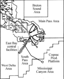
By the fall of 1977, the pipeline design including riser was essentially complete, and a route to shore on the Southwest Pass of the Mississippi River had been selected. Plans called for a 27.5-mi transportation system that would run from Mississippi Canyon block 194 to Shell’s production facilities on the east bank of the Southwest Pass of the Mississippi River Delta. Nearly 24 mi of that system would be offshore, laid in the deepest waters that the industry had faced to that date.
Pipeline hydraulic studies were made for both single-phase and two-phase flow conditions and various lines sizes, and the costs of the resulting pipelines were estimated. On the basis of forecast production, one line with a 12-in. diameter was selected for the two-phase flow that would exist during the first three years of “produce-while-drilling” operations. Later plans would see the construction of a second pipeline, which would then carry single-phase oil production.
With the deeper waters, designers opted for a relatively thick-wall pipe coated with thin-film epoxy, rather than thin-wall pipe coated with concrete and other materials, which had been the traditional offshore design for years. The new coating and weighting design was selected as the best for internal and external pressure conditions; bending during laying; potential mudslides; and possible hurricane-induced events. Seamless pipe was specified for offshore, due to the lower frequency of failures during hydrotest in comparison with ERW pipe and the high cost of repair offshore.
The offshore pipeline route included several sinuous curves through South Pass blocks 27, 37, and 38, which were designed to avoid specific bottom hazards. These route undulations added about 4% slack to the pipeline length in this area. The pipeline route was selected on the basis of accessibility to existing pipeline facilities and by the requirement to minimize potential hazards due to soil movements which were prevalent throughout the Mississippi Delta area. Numerous pipelines had been broken by mudslides and other unstable soil conditions in the Mississippi River Delta area, particularly near the mouths of the principal river passes where large volumes of soft silt and clay were deposited each year.
In January 1977, Shell asked R.J. Brown & Associates to assess possible construction methods. A phase one study resulted in Brown’s recommendation of the bottom tow method as the least hazardous and least costly installation method. A phase two study, performed in October, optimized the bottom tow procedures and refined the estimated costs for the Cognac pipeline project.
In December, Shell received construction proposals from several offshore contractors, and obtained cost estimates for pipeline construction using a reel barge; a third generation laybarge; and a traditional laybarge modified with a new deepwater anchoring system. After these discussions, the bottom-tow method was eliminated due to cost considerations, and because the method was judged to be vulnerable to the effects of a hurricane.
There was still a concern that the traditional S-lay technique might place too much strain on a curving pipe as it was laid off the barge, given the water depths that were being considered. But Langner convinced McDermott’s engineers that it would be permissible to have a tight overbend curve on the pipe if the steel properties were known, and in May 1978 McDermott won the bid.
McDermott utilized their newest laybarge, the LB-29, to install the offshore pipeline. The LB-29 was a traditional center-slot laybarge that had been equipped with a conventional five-segment articulated stinger.
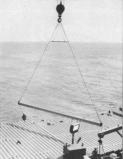
The use of an articulated stinger for the Cognac pipeline was not a first for the offshore industry. In this case, the stinger was licensed to McDermott under a Shell patent co-authored by Carl Langner. He had originally developed the articulated stinger concept on his first assignment at the Shell Pipeline Research and Development lab in 1967 and 1968. The basic function of the stinger was to cradle the pipe on a series of rollers as it left the laybarge and support the pipe in the “overbend” until the pipe could safely sag down to the sea bottom.
Langner noted that the stinger used for the Cognac pipeline was McDermott’s stinger No. 20, a North Sea-type stinger, which meant that it had a larger and deeper cross-sectional area than stingers normally used in the Gulf. McDermott decided on this stinger as a safety measure. “The contractor did not want any failures, especially in the record water depths encountered on this project,” said Langner.
The stinger had five sections, hinged together by special flexible connections. The stinger was controlled by pumping either air or water into the sections in order to maintain the stinger in a 700-ft radius arc. In this deepwater configuration, the stinger curved down from the stern of the barge to a maximum depth at the tip of about 140 ft, and a maximum angle of about 40 degrees. In shallow water, the stinger straightened out, becoming less deep, and so continued to maintain the pipe in a smooth “S-curve” between the barge and the seabed (and hence the term “S-lay” for this style of installation).
The anchoring and mooring system on the LB-29 was adapted so that it could operate in 1,000-ft water depths. As modified, the system consisted of twelve 40,000-lb anchors each connected to the laybarge by 135 ft of chain and 6,500 ft of wire cable. With up to 6,500 ft of 2¼-in. wire cable, plus 135 ft of chain between barge and anchors, this was the largest mooring system that had been used in the Gulf of Mexico. At the appropriate times through the pipe assembly process, tugboats moved the twelve 40,000-lb anchors and associated chain and wire line according to a precise plan which allowed the barge to position itself along the pipeline route. Walker described the operation: “The barge moves on its anchors,” he said. “To move forward you must pull in on the six forward anchor lines and pay out the six stern anchor lines. At the same time, the pipe is gripped in a pair of tension machines which apply up to 100,000 lbs to tension the pipe. It is imperative that constant tension be maintained on the pipeline, even when the barge is moving, in order to keep it from buckling.”
The line pipe was supplied by Sumitomo Metal Industries of Wakayama, Japan, and was magnetic-particle inspected and coated at the Bayou Pipe Coating Co. yard in New Iberia, Louisiana. Except for 36 joints of riser pipe, all offshore line pipe was externally coated with thin-film thermoset epoxy coating (Pipeclad) supplied by Cook Paint and Varnish Co. For corrosion protection, special devices installed on the Cognac pipeline included a Ziefle insulating coupling, located on the seabed approximately 200 ft away from the mouth of J-tube; and 120 zinc anode bracelets spaced uniformly along the offshore portion of the pipeline. The insulating coupling provided electrical isolation from the platform, and the anodes provided cathodic protection for any coating defect that might exist along the pipeline.
Because the line was designed for two-phase flow – transporting both oil and gas – the team proposed using a 12-in. pipe, which was a somewhat larger diameter than what would have been needed for oil alone. That led engineers to think about what kind of pipe they needed for these depths and pressures.
As the project ramped up, Wilkinson explained the rationale behind the choice. “We chose to go with a heavy steel pipe (up to 0.688-in. wall) rather than a thin-wall pipe wrapped in concrete. While the thicker steel wall costs a little more, the heavy pipe solved two problems,” Wilkinson noted. “It allows us to apply a stronger grip to the pipe without collapsing it in the tension machines that that hold it on the laybarge, and it gives the pipe more resistance against buckling from bending and external pressure in deepwater,” Wilkinson added. “One thing we’re trying to avoid is buckle propagation – the process by which the pressure of the surrounding water will cause a flat spot to spread out and run along the pipe and flatten the whole piece. Using the wall thickness we’ve chosen, this phenomenon will not occur; the pipe could buckle but the damage will not propagate.”
While the use of this heavy pipe eliminated the need for a weight coating, the pipe still needed the protection of a corrosion coating. A thin-film fusion bonded epoxy coating was chosen for this project. A product of Cook Paint Co., this coating used resins developed by Shell as its primary ingredient. It was applied to the pipe in the coating yard before the pipe was loaded onto barges to go offshore. Langner described the process of preparing the pipe for coating: “To apply the coating, the pipe is first shot-blasted with little metal pellets so that all the rust and scale are removed and the metal is cleaned to a bright finish,” he said in May 1979. “The pipe then passes through a furnace where it’s heated to about 500°F and the epoxy powder is sprayed onto the hot pipe. In a matter of a few seconds, the reaction in the chemical compound hardens the powder into a coating. It looks like paint but it adheres very strongly to the pipe.”
The design and installation of the riser was a key part of the project, because it represented the part of the pipeline which ran up from the seafloor to the top of the platform. As such, it had to be coordinated with the design of the platform. But designing a riser for the world’s tallest platform presented a significant challenge. After reviewing options, the decision was made to go with a conventional J-tube riser. Since the platform was built in three parts, the J-tube conduit was also built as three separate conduits. As a result, there were gaps in the J-tube conduit where salt water could flow in and out of the conduit. To help prevent corrosion, a special quarter-inch thick neoprene coating called Splashtron was applied on the riser pipe. It was the first time that Shell had used this material to coat an entire riser pipe.
There were several new technologies deployed on the project. These included an electronic navigation system, complete with minicomputer and CRT readout, to guide the laybarge along the pipeline route; a cable-pulling machine with a special pipeline pull head to pull the pipe from the lay barge down to the sea bottom and then up through the J-tube conduit; and two unmanned underwater vehicles, Taylor Diving’s RCV225 and McDermott’s TROV, which assisted in the installation of the messenger wire through the J-tube.
On May 5, the LB-29 began its journey (via tow) from Bayou Bouef, Louisiana, for the 40-mi trip to the Cognac platform. The laybarge arrived at the platform the next day, and proceeded to run anchors. Offshore pipelay took place between May 11 and May 27 with an average lay rate of 1.26 mi per day and a maximum lay rate of 1.59 mi per day. Interestingly, the progress was greatest in the deeper waters where the modified anchor system worked best. The J-tube riser was successfully installed on May 10.
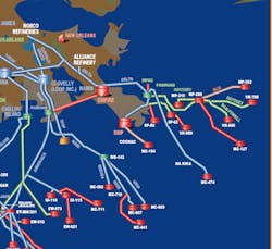
Meanwhile, work on the onshore portion of the project was also wrapping up. Construction contractor H.B. “Buster” Hughes & Co. completed the 3-mi onshore segment of the system, connecting the pipeline at Southwest Pass into the Delta system at the East Bay facilities, for the eventual transportation of Cognac production to the Norco refinery.
Regulations required offshore pipelines to be buried 3 ft in the seabed in waters less than 200 ft deep. Thus, a second pipelay spread, consisting of McDermott’s spud barge Marc I and two dredge barges, laid pipe from the shoreline to the 200-ft depth contour, where the laybarge could perform a tie in. McDermott’s trenching and burial barge Jirafa buried the pipeline from shore to the 200-ft water depth mark. Ultimately, some 37,000 ft of pipeline was installed and buried in this shallow-water portion. The spud barge reached the tie-in location on the morning of May 27, and the tie-in was performed that afternoon. The pipeline was successfully hydrotested for 24 hours on June 8-9, and first production flowed in September.
One device that proved particularly valuable to the project was the electronic positioning system used to guide the laybarge along the pipeline route. Leased from John Chance & Associates, this system was based on an Autotape survey instrument on the laybarge with transponders on several nearby platforms. Coupled into this system were a minicomputer preprogrammed with the desired laybarge route coordinates, and a CRT display unit in the laybarge tower for guiding the anchor winch operators. The system provided simple “go left” or “go right” instructions to the operators and was well received by all those onboard the LB-29.
The use of two unmanned underwater vehicles in these water depths was also a first for the Gulf of Mexico. Taylor Diving Co. provided its saturation diving system and a team of divers standing by on the barge “in case we dropped a cable and had to pick it up, or if we had to do work on the pipe while it was on the bottom,” Wilkinson said. As it turned out, the divers never had to be called into action. Instead, two remote-controlled vehicles were used mainly for observation, but they were also employed for some subsea construction work.
One of these, Taylor’s RCV 225, was essentially an underwater observation unit, employing a television camera and electrically powered thrusters to maneuver it from place to place. The other underwater vehicle was McDermott’s TROV. It was equipped with two television cameras, and electrically powered thrusters enabled it to maneuver from place to place. The TROV also had two manipulating arms which were able to do a certain amount of work.
The use of “underwater robots,” as they were first called, was still in its infancy for the offshore oil and gas industry. “We’d never used either of these on a pipeline job before,” Langner said. He cited one of their key uses during the project, on the construction of the J-tube riser system. “Before we could run pipe by the J-tube, we had to run a messenger wire down the tube and out to the laybarge,” Langner explained. “When we installed the wire in the J-tube, we used the RCV to verify that the wire indeed was properly in the tube. To retrieve the wire, we dropped a hook down over the stern of a work boat and positioned it just outside the end of the J-tube, which is 10 ft off the bottom or 1,010 ft below the water surface. Then we ‘flew’ the TROV down to the mouth of the J-tube, grabbed the hook with one of TROV’s manipulator arms, and connected the hook into an eye on the end on the end of our messenger wire. Then all we had to do was pull the wire up to the workboat. Due to the increasing restrictions placed on divers today, these unmanned vehicles are becoming increasingly popular in performing services which divers used to do.” It would be a prophetic statement as the industry continued to move farther out into deepwater.
The timely and successful completion of the Cognac pipeline was attributed to the selection and use of high-quality materials, particularly the Sumitomo line pipe; good weather conditions throughout the offshore construction period; no major breakdown of critical construction equipment; and careful planning and execution throughout the project by both McDermott and Shell. The pipeline initially was used to transport two-phase gas-oil production from the Cognac platform to shore. Later, after the installation of a second pipeline, the original system would be used to transport single-phase crude oil with a maximum throughput of 50,000 b/d.
As might be expected when dealing with superlatives, building the world’s deepest offshore operating pipeline was an expensive venture. “Our major costs and the major amount of time consumed were not during the pipelaying itself, but rather during the preparations and during the various pipeline tie-ins,” Wilkinson observed. “Because the laybarge itself is primarily a floating pipe factory, it welds pipe together at a very fast rate.” The team members estimated the “spread” cost to be approximately $125,000 per day while laying pipe, including the team of contingency divers on board. The Cognac pipeline system – the riser, the pipe, the onshore tie-in – had been authorized for $16 million, but the actual costs were less than $12 million.
Life on the barge
With a supporting crew of more than 200 men, the “floating pipe factory” on the LB-29 traveled at a rate of about a mile and a half per day, producing as much as 14,000 ft of finished pipe in that timeframe. The crew, including both McDermott employees and Shell Pipe Line inspectors, worked two 12-hour shifts, one beginning at 11 am and the other at 11 pm. Their routine was often tedious, but nevertheless required constant attention.
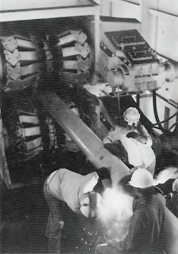
“Go-Devil,” an internal publication of Shell Oil Pipeline Co., covered the project in depth in May 1979, as the pipeline was being installed. The article provided a detailed glimpse of life on the laybarge during the time of the project. The author wrote: “To the casual observer, the assembly line was something to see. Every six to seven minutes one section of pipe is rolled into place at the beginning of the assembly process. Welders at the bead station make the pipe’s first attachment to the line.”
“These welders work constantly for the entire time limit, putting on as much weld as possible,” said R.L. “Reggie” Prather, a Shell senior inspector. “We’re using the most up-to-the minute stick rod welding technology, but it’s not anything unusual, not like some of the exotic methods used in the North Sea.” Bill Moates, Shell’s construction superintendent in charge of the barge, estimated that assembling the Cognac line required approximately 20,000 pounds of welding rods, deployed at a rate of 28 to 30 rods per weld.
The article continued: “The barge’s whistle blows, the crewmen in the control tower engage the anchor winches, and the barge makes a 40-ft step toward land, which takes about 45 seconds. During the move, another piece of pipe is rolled into place. The joint attached about 30 minutes ago has reached the x-ray station for a final pass on inspecting the weld. On one side of the barge, a crane operator is continuously supplying the joints from another barge pulled up alongside the LB-29, sometimes as many as 280 per day. Six more minutes pass. The pipe is now in the domain of coating inspector Richard Lopez. A McDermott crewman in what looks like the latest in space suit designs from NASA fuses an epoxy coating to the weld area of the joint. It passes from vision as it moves out of the stinger on its journey to the mud at the bottom of the Gulf.”
Following this routine for 12 hours, “a guy has to be ready to take a break,” the article noted. Richard Lopez was just getting off the 11 pm to 11 am shift when he made these comments about life on the barge: “Because we’re out here for 14 days at a time [followed by seven days off], you get familiar with the different lifestyle pretty quickly. Even if it’s a guy’s first time out, he’s able to readjust his body clock to the routine.”
Lopez elaborated on the lifestyle: “I’ll eat when I get off. Meals are served every six hours. If you just sit around, it’s easy to gain weight. So I try to get some exercise every day. We have a little weight room where we can jump rope, or lift weights, or play ping pong. Then, I’ll talk to the guys, or go to the movie if it’s one I want to see.” As part of the latest amenities of offshore life, the LB-29 housed a mini-theater where movies were shown several times during the day. At about two o’clock in the afternoon, Lopez would retire to the bunk room he shared with three other crewmembers to try and get some rest. He would get up about 9:30 pm, eat a meal, then resume inspecting coatings.
Bill Moates, being the decision-maker, problem-solver, and “official in residence” on board, maintained an even more hectic schedule. Over a steak lunch, he described his schedule: “When we’re pulling a riser, or when crossing another pipeline, it’s not unusual for me to go to 72-hour stretches without sleep. If I get five hours sleep, I consider it a good night. People are [often] coming to me with questions, plus I just like to keep an eye on the operation.”
Cognac’s significance
Once it had been completed and placed in the operation, the Cognac project received numerous plaudits for setting new deepwater engineering and construction milestones. In 1980, the project received the Outstanding Civil Engineering Achievement of 1980 award by the American Society of Civil Engineers; and in 1982, the project won the OTC Award for Engineering and Installation Excellence.
Shell continued to drill new wells at the Cognac field. By 1981, Shell had two drilling rigs working the field, and 61 wells had been drilled and 36 wells had been completed. That same year, a 16-in. gas pipeline was installed by Southern Natural Gas Pipeline Co. that ran 20 mi to South Pass block 22, tying into Southern Natural Gas Romere Pass Pipeline. Upon completion of this gas line, the Cognac pipeline reverted to a single-phase crude oil pipeline.
The Cognac project proved that deepwater production was technically feasible and economic in the Gulf of Mexico. While the amount of pipeline installed was relatively small, its successful design, installation and operation was a major milestone for the industry. Previous underwater systems had been installed in 300 to 400-ft water depths. Cognac represented an exponential increase in water depth capabilities for the offshore oil and gas industry. •
References
1. Carl G. Langer and Harry Wilkinson, “Installation of the Cognac 12-inch pipeline” (OTC 3740, 1980).
2. “Superlatives abound as Cognac hits new depths,” Go-Devil (Shell Oil Pipeline Co. internal publication), May 1979, pp. 1-5.
About the Author

Bruce Beaubouef
Senior Lead Reporter / Managing Editor
Bruce Beaubouef is Managing Editor for Offshore magazine. In that capacity, he plans and oversees content for the magazine; writes features on technologies and trends for the magazine; writes news updates for the website; creates and moderates topical webinars; and creates videos that focus on offshore oil and gas and renewable energies. Beaubouef has been in the oil and gas trade media for 25 years, starting out as Editor of Hart’s Pipeline Digest in 1998. From there, he went on to serve as Associate Editor for Pipe Line and Gas Industry for Gulf Publishing for four years before rejoining Hart Publications as Editor of PipeLine and Gas Technology in 2003. He joined Offshore magazine as Managing Editor in 2010, at that time owned by PennWell Corp. Beaubouef earned his Ph.D. at the University of Houston in 1997, and his dissertation was published in book form by Texas A&M University Press in September 2007 as The Strategic Petroleum Reserve: U.S. Energy Security and Oil Politics, 1975-2005.