Honey Comb Base bulk storage tanks for drill cuttings improve efficiency, safety in zero discharge operations
Ron Morris, Simon Seaton - Halliburton Baroid
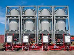
Current regulations require the containment and removal of drill cuttings generated with oil-based systems, from a drilling rig for ultimate disposal. Proposed legislation may prevent the discharge of water-based cuttings as well, which will further contribute to the growth of “zero discharge” or “ship-to-shore” operations. While there are several types of storage methods currently in use, none provides a truly cost-effective and efficient method for cuttings containment and transfer at the disposal point. A new system using a Honey Comb Base (HCB) tank design has improved significantly on conventional systems by increasing efficiency and ultimately reducing disposal costs. The HCB tank system is deployed in the North Sea where four HCB tanks replace approximately 200 cuttings boxes in an effort to increase rig deck space. A major operator has scheduled another North Sea installation of the HCB tank system this fall to facilitate inter-field cuttings transfer and disposal
null
Issues with conventional cuttings storage and transfer
Prior to the introduction of the HCB tank, operators relied on several methods in the cuttings storage and transfer process, particularly cuttings containers - cuttings boxes or skips. The commonly used containers have a capacity of four to eight tons. Cuttings boxes occupy valuable deck space on the rig, and many rigs never were designed for cuttings storage and transfer operations. More importantly, multiple crane operations are required to move these boxes, resulting in risks for both worker safety and the environment. In a typical offshore operation, where about 1,000 tons of cuttings are generated, cuttings boxes must be lifted onto a boat, transported, lifted onto the rig, and later moved to the shaker area for filling. Once filled, the process is reversed. Each box is lifted at least six times, resulting in as many as 1,200 crane operations per well. Operators have tried using larger boxes to reduce the number of lifts. However, the increased weight of these boxes creates other issues because they typically cannot be handled by forklifts and may require higher rated cranes which may not be available.
Bulk storage tanks such as those used for barite and cement, can eliminate the need for cuttings boxes and offer a fully enclosed, zero discharge system. Using bulk tanks for cuttings storage on an offshore rig allows for the direct transfer of cuttings and liquids to boat storage tanks via hoses by either pneumatic techniques or pumps.
However, an effective, universal bulk storage system has been slow to develop owing to the constantly changing size, shape, and consistency of drill cuttings. Because formations differ, cuttings in the Gulf of Mexico differ from those in the North Sea. Even within the same area, cuttings can differ substantially. A close look at each of the bulk storage configurations currently in use reveals the limitations of each - limitations that can delay operations and increase the risk of non-compliance with regulations.
Rat holing. The most common bulk systems have tanks which are loaded from the top and discharged via pneumatic pressure through a single cone arrangement at the base. These tanks are similar to the conical bottom tanks used to transfer dry bulk material such as barite. They are relatively simple to construct with few moving or mechanical parts. However, single-center discharge tanks can bridged off, become blocked, due to the nature of drill cuttings., Cuttings tend to create their own plastic cone within the mass of cuttings while seeking the path of least resistance during discharge. This effect, known as the “rat holing,” can reduce storage efficiency by as much as 60% and leave a considerable amount of material behind. High-angle conical tanks have been designed to address this, but they may reduce the relative capacity of a tank with a given footprint.
Mechanically assisted tanks. These pneumatic bulk storage systems incorporate a mechanical agitation system to assist the exit of the cuttings from the base of a single center discharge tank, which reduces the chance of bridging or rat holing. Typical components used to break up the cuttings are internal agitators, screw type augers, or sliding tank bases. While more efficient, these systems increase both manufacturing costs and the risk of mechanical failure.
Cuttings slurry tanks. Unlike pneumatic systems, this technique uses liquid, usually water, to slurrify cuttings prior to pumping the slurry from rig storage tanks to boat storage via centrifugal pumps. This is effective if the cuttings are destined for injection into a disposal well, but it increases overall disposal costs by increasing the volume of waste material, cuttings, and contaminated water to be transported and disposed. A further disadvantage is the need to prevent cuttings from settling during transportation. This requires continued agitation or the addition of suspension additives.
Honey comb design. The multiple outlet discharge system design based on a HCB tank provides a solution to the “rat holing” and blocking of single discharge tanks. The HCB tank was developed specifically for the reliable discharge of bulk materials from pneumatic silos. These materials range from dry powders such as fly ash and cement, to high-moisture, viscous type materials such as sewage sludge.
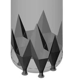
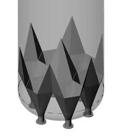
The HCB tank design includes a multiple discharge point arrangement. Typically, six outlets are arranged in a honey comb design at the discharge base of the tank. The multiple hexagonal discharge outlets are arranged internally around a large inverted hexagonal spike that stretches up into the tank. This inverted spike acts as a breaking device to ensure the material is broken up as it passes down the tank, and it helps direct the cuttings to the discharge outlets, ensuring flow of the material out of the tank and eliminating rat holing down the center of the tank.
The tank discharges cuttings by applying compressed air to the top of the cuttings like traditional pneumatic tanks. The air on top pushes the cuttings down and out the outlets in the base. In addition, air also is injected into the base of HCB tank to mechanically break up and fluidize the cuttings as they pass toward the hexagonal outlet, eliminating the need for additional mechanical agitation and the risk of mechanical failure.
Cuttings discharge is timed per each discharge point to ensure even flow out of each outlet. The discharge valves are opened and closed in a predetermined sequence for a specific period of time, rotating around each discharge point. The discharge of cuttings is evenly spread around the base of the cuttings in the tank, in effect removing this base and allowing the cuttings to constantly fall down into each outlet.
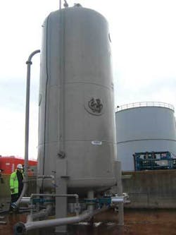
The HCB base is designed to fit into a standard ISO frame tank to simplify the design and certification of the tank itself. By maintaining the integrity of the tank through a standard “dished end” design, the cost and certification of this tank has been kept to a minimum. The nominal capacity of each tank is 113 bbl (18 m3) or approximately 41 metric tons of cuttings per tank at a bulk density of 19.2 ppg (2.3 s.g.). However, for fixed systems built into platforms or new-build rigs, the size and capacity of the tanks can be greater.
Intra- and inter-field transfers
An area of particular interest for the use of HCB tank systems is in the intra- and inter- field cuttings transfer. The ability to recover cuttings generated at one offshore location and transfer them to a second offshore location for disposal, either through cuttings injection or though offshore thermal processing systems, is becoming a focus of development in a number of areas around the world. A significant aspect of offshore cuttings transfer will be the ability to transfer cuttings from a rig to a boat, then from the boat back up to a second rig or platform for disposal. In some cases, this could require transferring the cuttings from the storage tank over 150 ft.
The HCB tank system was tested prior to its commercial release. The primary test objectives were to store cuttings in the HCB tank and to pneumatically discharge them completely from the tank to a receiving location with no slurrification or addition of liquid. A detailed account of the test results is shown in Tables 1 and 2. The testing was done over a five-month period, first at the fabricator’s yard in the UK and later at an onshore oil supply base in Peterhead, where all tests were witnessed by UK-based operator staff. The oil-based mud cuttings were supplied by a major UK operator as representative of North Sea cuttings. The HCB tank system was set up on the base and all interconnecting pipe work, air lines, cuttings handing lines, etc. were rigged up within a bunded test area.
| Discharge Line Diameter | 5 in. (125 mm) |
| Horizontal Distance of Loop | 334 ft (102 m) |
| 90-degree Bends in Loop | 6 (1.5 m radius) |
| Air Pressure inside HCB Tank | 60 psi (4 bar) |
| Conveying Line Pressure | 40-60 psi (3-4 bar) |
| Transfer Rate Achieved | 48 tons per hour |
| Discharge Line Diameter | 5 in. (125 mm) |
| Vertical Height Pumped | 180 ft (55 m) |
| Total Distance Pumped | 393 ft (120 m) |
| 90-degree Bends in Loop | 6 (1.5 m radius) |
| Air Pressure inside HCB Tank | 75 psi (5 bar) |
| Conveying Line Pressure | 60-88 psi (4-6 bar) |
| Transfer Rate Achieved | 30 tons per hour |
The tests were conducted to ascertain the horizontal and vertical transfer capabilities of the HCB tank system. The key objectives were as follows:
- Determine horizontal distance cuttings can be transferred pneumatically from the HCB tank
- Determine the rate (metric tons per hour) at which cuttings can be transferred from the HCB tank
- Confirm that cuttings can be transferred 180 ft (55 m) vertically (the height from a boat to rig or platform)
- Leave cuttings for extended period of time (> 1 week) in HCB tanks and then re-establish discharge without blockages
- Ensure the HCB tank can be discharged completely without blockages.
A crane was used to simulate the height pumped from the boat up to the platform deck. Upon completion of the horizontal and vertical pump trials, the cuttings were pumped back into the HCB tank and left in place for seven days without agitation or movement. After seven days, the same set of tests were conducted, pumping the cuttings horizontally and vertically with the same results achieved.
Conclusions
The results of five months of testing and the ongoing North Sea operations (where the HCB tank system has replaced cuttings boxes) show that the HCB tank system is ready for the cuttings storage and disposal challenges facing operators today.
- All cuttings in all transfer operations were pneumatically discharged from the tank with no “rat holing” or material left in the tank, demonstrating full storage and discharge capability from the tank.
- The HCB system handled cuttings of varying consistency from dry to wet and showed no signs of blocking the discharge ports of the HCB tank.
- Cuttings were discharged horizontally at distances in excess of 300 ft (100 m) through a 5-in. line at a rate of 48 tons per hour.
- Cuttings were discharged vertically at heights in excess of 180 ft (50 m) through a 5-in. line at a rate of 30 tons per hour.
- All test objectives were met with no need to slurrify cuttings and no blockages of the discharge ports of the HCB tank.


