SEISMIC ACQUISITION: Marine seismic survey positioning and control requirements evolve
Complex 3D arrays require new 'bird' solutions
Dale Lambert
Robert J. Leger
Charles J. Ledet
DigiCourse
Seismic exploration seeks to answer the question, "Is there oil down there?" For marine seismic positioning, the next question becomes, "Where is there?"
null
Marine seismic exploration assists oil companies in locating hydrocarbon reserves in marine environments. The method of locating these reserves varies due to the marine environment and location of the survey area.
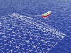
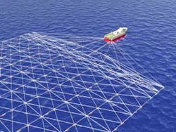
In deepwater marine seismic, a survey vessel tows an array of sensors (hydrophone streamer cables) through the water at an average speed of 4-5 knots and fires a seismic source array (airguns) every 6-13 seconds to map the geophysical attributes of the subsurface. Acoustic energy created from the discharge of compressed air into the water travels to the ocean floor and begins a series of refractions and reflections off multiple subsurface layers.
Reflected energy travels back to hydro-phones installed in streamer cables towed behind the vessel. This information is digitized and recorded on storage media. Geophysicists use these data to detect the presence of hydrocarbon reserves.
During the seismic data acquisition process, marine positioning equipment provides acoustic, compass, and depth measurements so seismic data processors can tie navigation and location data to geophysical data to determine the location of potential reserves for precise drilling operations.
History
J.M. Lapeyre invented the optical-digital compass during the 1960s and formed DigiCourse to manufacture it in 1971. Thereafter, 2D marine seismic streamer positioning used externally mounted depth control and magnetic compasses (compass birds) to control streamer depth and to measure the towed streamer's heading. These observations helped to approximate cable shape and hydrophone locations.
The compass
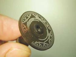
The optical-digital compass is based on an optical code card. This code card floats on a common shaft with a simple magnet. The case is attached to a gimbaled assembly containing arrays of light emitting diodes (LEDs) and phototransistors. As the relative position of the arrays and code card changes, different LED light paths are blocked from the phototransistors. The heading can be resolved to a resolution of roughly 0.3°.
null
The compass measurement is repeatable to about one-half of a bit or 0.18°. Because of its gimbaled system, the optical compass operates uniformly between all but the most extreme latitudes (poles), or anywhere in the world where towed array seismic exploration is practical. The optical compass' calibration is very stable over time because it is a digital device.
Positioning
By the late 1980s, a new method of seismic data acquisition, dual streamer with dual source, was able to produce multiple common midpoint (CMP) lines, thus increasing operational efficiency. With the advent of multi-streamer 3D seismic operations, Compass Birds alone were insufficient for the positioning resolution required for multi-streamer acquisition. Acoustic ranging systems were then used to augment heading and streamer shape estimates. By the 1990s, 3D seismic became common, and typical positioning systems employed acoustic networks at the front, middle, and tail of the streamers.
Streamer counts continued to increase, and streamers continued to grow in length. Oil companies were interested in looking at smaller and deeper reservoirs. Corresponding improvements in positioning accuracy were required. At the 1997 Hydrographic Society meeting in Scotland, Dr. Chris Walker presented a paper co-authored with Jon Falkenberg of PGS Exploration. The paper, titled "Acoustic Positioning of Seismic Streamers," described tying the then separate front, middle, and tail acoustic networks together. This was achieved by populating each streamer with acoustic devices down the entire array. This method became known in the industry as full acoustic cross bracing.
Comparing full cross bracing
Common positioning requirements are based on estimated acoustic node positions and are typically 5 m at the front and tails of the streamers and 12 m in the middle of the streamer. Positioning errors are lowest at acoustic nodes located closest to the GPS locations (seismic vessel and tail buoys). Since there is a limit to the practical acoustic range lengths, cumulative range errors have their largest impact in the middle of the streamer network.
To compare the effectiveness of full cross bracing with typical front, middle, and tail acoustic configurations, simulations were run using an industry-accepted network analysis package, GeoMatrix by Concept Systems Ltd. The figure shows a six-streamer, 8-km network with front, middle, and tail acoustic networks. Streamers are evenly spaced 100 m apart. On the left side, only the first three rows of acoustics are visible. On the right, the entire network is visible. The blue circles illustrate nodes. Green vectors illustrate range observations made from node to node. Green ellipses around the nodes are called error ellipses and represent expected horizontal node position errors at a single standard deviation.
null
The diagrams show that, due to geometry, the error perpendicular to the streamer (cross line) is worse than in the parallel (in line) direction. Data presented here is in terms of the worst case (mid-cable) error ellipse major diameter at one standard deviation and a GPS uncertainty of 3 m.
Compasses are modeled as bearings from one node to the next on a particular streamer and are given a 0.5° standard error. Modeling a compass, as a bearing from node to node, may not reflect post-processing techniques used by particular contractors, but should be useful for comparison here.
Typically, compasses are placed every 300 m down the length of a streamer cable. At the front, middle, and tail, acoustic observations are made in a crosshatch pattern. All range standard deviations in this model are one meter plus 0.05% of the nominal range distance. For a typical system with front, middle, and tail acoustic networks, the worst case node position error is roughly 5.8 m, which is an acceptable uncertainty.
In rough weather, compass performance can become noisy due to accelerations on the streamer. This effect is modeled by increasing the standard error for compasses in the simulation model. If the compass error is increased in the model to 2°, the corresponding worst case node error increases to 18.2 m, which does not meet usual positioning specifications.
Acoustic cross bracing
For the full acoustic cross bracing example, the hatch pattern seen is repeated all the way down the cable to the tail buoy. The worst case node position error is 10.2 m with no compasses. By adding 0.5° precision compasses every 600 m, the positioning error reduces to 4.7 m. If we again increase the compass error in this model to 2° to simulate the effects of rough weather, the corresponding worst case node error is only 9.1 m. This combination would provide acceptable positioning results required for seismic operations, even under adverse weather conditions.
Compass heading and acoustic range observations are complementary information. A survey network that contains both observation types will always be more robust than a network with only one type. And there are other practical considerations. When seas are calm, shallow, or have high algae content, acoustics can experience dropouts due to multi-path, ray bending, or attenuation. Today's acoustic systems are also only usable when fully deployed, which means that compasses are still required for streamer deployment and retrieval operations.
null
More acoustic ranges in each shot interval can improve the positioning solution; however, there are limits to how many acoustic observations can be made in a given time interval due to interference. This is especially challenging because acoustic signal bandwidth is limited by the physics of sound traveling in water. Separating signals in time, space, and frequency are all choices to increase the amount of ranges in a given shot point interval. Advancements in spread spectrum and digital signal processing (DSP) techniques serve to increase range signal to noise ratio. New acoustic signal sets combine all of these techniques to maximize acoustic channel count, range accuracy, completion rates, and practical distance.
Economic, operational challenges
The conventional technique of full acoustic cross bracing has created both economic and operational challenges for marine seismic exploration. Increasing the acoustic network density requires significant capital equipment expenditures. This includes additional acoustic devices, spares, and peripheral support hardware (float tubes, batteries, and collars).
null
Operational considerations pose serious productivity challenges that can include:
- Modifications to the vessel's back deck to accommodate a higher volume of acoustic device storage
- Increased streamer deployment and retr-ieval time
- Increased streamer drag
- Increased liability exposure during small boat operations.
The cost of conventional full acoustic cross bracing is not economically or operationally attractive in a weak seismic market. A new creative solution to improve positional accuracy is required.
New solutions
A new method of achieving full acoustic cross bracing while maintaining streamer control is the replacement of a number of existing compass birds with acoustic birds. Combining acoustic ranging capability with the industry standard cable leveler allows extension of acoustic networks and improved positional accuracy without the negative economic and operational drawbacks of using conventional acoustic-only devices to implement full acoustic cross bracing.
DigiCourse's acoustic positioning solution, DigiRange, has achieved operational excellence during the past 10 years of service using DSP and spread spectrum techniques for acoustic positioning. DigiRange II and the Acoustic Bird will incorporate further enhancements to the DSP algorithm and signal sets allowing greater reception and correlation of the transmitted signals, increased channel count, and reduced overall cycle time
The future
In today's competitive seismic market, contractors want to delay large capital investments and extend the value of equipment they already own. Fortunately, acoustic conversion kits for the Compass Birds can deliver benefits of full acoustic cross bracing today without adversely impacting productivity and economic efficiencies. This approach allows efficient use of deployed capital while development of future positioning systems continues.


