New tool enables cost-effective multilateral re-entry
By Ademola Otubaga,
Faraj Benhamad,
Husam Helou,
Henry Wortmann
Schlumberger
The decision to prepare multilateral wells for later re-entry traditionally had to be made during initial well design, before confirming that production data warr-anted the investment. The potential necessity for wellbore cleanouts, formation damage removal, acid stimulations, nitrogen lifts, or wellbore logs was just too great to avoid upfront installation of sophisticated completion hardware. Thus, Technical Advancement of Multilateral Wells (TAML) levels 3 to 6 completions - described as re-entry enabling - had to be installed, adding to the complexity of the wellbore construction and completion process. In addition, the investment had to be added to overall wellbore costs.
This practice undercut the advantage that multilaterals offered the industry of minimizing costs per length of pay zone. But if multilateral wells were completed without re-entry-assisting equipment, this meant that formations could not be stimulated selectively or could be stimulated only after going through time-consuming, trial-and-error access methods on jointed pipe or coiled tubing. Inefficient fluid treatment and extended nonproductive times pay out late or simply do not justify the production enhancement investment at all.
Lateral re-entry technique
A means was needed that allowed selective re-entry to the lateral branches of a multilateral well, regardless of its completion. Assuming that most lateral branches are horizontal, this method should function on coiled tubing. Further assuming that the preferred well configuration is the openhole wellbore, the re-entry device had to function reliably, even in wellbores that had ledges, washouts, and the like. Finally, the re-entry technique had to be reliable and fast, reducing overall treatment costs and enabling quick payback.
Schlumberger developed a new lateral re-entry technique that provides access to all levels of multilateral wells - including the ability to selectively enter levels 1 and 2 lateral extensions. Only recently have operators been able to take advantage of coiled tubing as a means of selectively entering live multilateral wells. This new technique does just that.
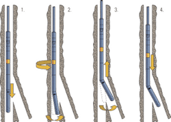
The new system design includes a re-entry bottomhole assembly (BHA), which consists of a surface-controlled orienting tool and a controllable bent sub (CBS). The system identifies the window of the selected lateral before attempting re-entry, and confirmation of successful identification and entry is visible at surface through a software-displayed pressure log.
The system works in conjunction with a rotational device, i.e., an orienting tool, above the CBS that rotates the CBS to change its orientation. The technique does not require a wired coiled tubing string. The corrosion-resistant re-entry system is operated solely on flow and is conveyed with standard coiled-tubing equipment.
Field examples from offshore Abu Dhabi are delineated in this article, proving again that this new technique enables reliable re-entry of a designated lateral on the first attempt for operations such as selective matrix stimulation and openhole formation wash treatments. In February, two offshore operations were executed using the Discovery multilateral tool (MLT) technique.
Bullheading
Traditionally, such stimulations involved a technique called "bullheading." This is a common approach for acidizing multilateral wells, if selective treatments are impossible. Bullheading the treating fluid from the surface is a gamble, assuming that the reactive fluid will reach into all laterals and treat the formation along the entire damaged interval.
There is no control of exactly where the fluid will go. Due to this lack of control, sections of high permeability and the heel of the lateral, which is the first area encountered by the fluid, tend to take most of the treatment, while the low permeability sections usually remain virtually untreated. Efficiency of these types of treatments is therefore limited.
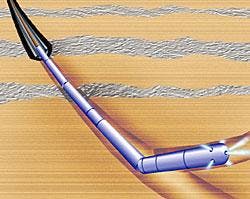
With the introduction of the new re-entry technique, operations such as openhole formation washes, selective matrix stimulation, production logs, and nitrogen kickoff operations can be performed effectively through coiled tubing on live, flowing multilateral wells. Once the lateral is entered, the stimulation nozzle, a hydraulically actuated pressure jetting sub, is placed across the zone of interest to perform a pinpointed treatment. The ability to access all levels of multilateral wells with coiled tubing adds a new planning and contingency option to the operator's and driller's decision matrix for the wellbore construction phases.
Abu Dhabi case study
Both candidate wells, located offshore Abu Dhabi, were chosen to be stimulated selectively with coiled tubing utilizing the MLT technique. A multipurpose service vessel (jackup barge) was used for this project.
Both wells were dual string, multilateral oil producers. Well No. 1 was completed with 7-in. casing, set at 8,473 ft. The production tubing installed had a minimum ID of 2.31 in. The horizontal openhole section was drilled as a three-leg lateral. The natural leg (leg 3) was an 8.5-in. openhole with TD at 10,246 ft. Both legs 1 and 2 (non-natural legs) were drilled as 6-in. openhole with TD at 9,158 ft and 10,152 ft, respectively.
The objective was to locate the non-natural leg 2 and stimulate it with 15,000 gal of 15% nitrified hydrochloric acid (HCL)using the MLT technique in conjunction with a ball drop circulation sub with imbedded high pressure jets.
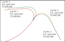
Well No. 2's long string (target string) was completed with 7-in. casing to 7,867 ft. The 2.875-in. production tubing was installed at 7,857 ft, having a minimum inner diameter (ID) of 2.31-in. The horizontal openhole section was drilled as a four-leg lateral.
The natural leg (leg 4) was a 6-in. openhole with total depth (TD) at 8,942 ft. The non-natural legs were drilled as 6-in. hole, leg 1 having a TD of 9,098 ft. Leg 2 and leg 3 both were drilled to 9,255 ft, which implied that tagging the laterals' bottoms alone would not identify them clearly. The objective for this well was to locate and stimulate the non-natural legs 2 and 3 with 10,000 gal of 15% HCl each utilizing the MLT technology in conjunction with a high pressure circulation sub.
Coiled tubing BHA design
The technical feasibility of the operation was studied utilizing CoilCADE software. The simulations showed that 1 3/4-in. coiled tubing was required. The components of the coiled tubing (CT) BHA consisted of a motor head assembly, incorporating a dual flapper check valve, hydraulic release, and a drop-ball circulating sub (with 6 x 0.093-in. inserted jets that were designed to create a pressure drop of 1,600 psi at 1.5 bbl/min). Also included were a downhole filter and the MLT tool. The maximum outside diameter of the tool was 2.125 in.
Procedure
In the first pass for well 1, the MLT toolstring was run straight past the junctions of legs 1 and 2 at 8,475 ft and 8,525 ft. After confirming that the CT had entered into leg 3, the natural leg, the BHA was pulled back to 8,600 ft to start the profiling procedure. The pump rate was increased to 1.6 bbl/min while profiling the window.
The pressure response from the tool and its relative bearing was monitored in the CT unit using the custom software. Eight passes were carried out and the window was clearly located at 225° relative bearing at 8,500 ft. The tool string was then run in to enter the window.
Having accessed the non-natural leg, the pump was stopped and TD was tagged to assure that the CT had entered into the correct lateral (leg 2). To maximize the pumping rate, a 0.625-in. ball was dropped to open the high-pressure circulating sub and begin the fluid treatment with high rate nitrified acid. After the acid treatment of leg 2, the CT was pulled back to surface.
In the first pass for well 2, the MLT toolstring was run in straight to the bottom of the natural lateral, leg 4, past the junctions at 7,867 ft (leg 1), 8,095 ft (leg 2), and 8,104 ft (leg 3). The CT was then pulled back to 8,150 ft to start the profiling procedure. The pump rate was increased to 1.6 bbl/min to profile the window while pressure signals of the re-entry BHA and its relative position were monitored in the CT control cabin through the custom MLT software.
The CT was then again run in, this time below the window to begin another pass. Ten passes were carried out, and the second leg was located at 300° at 8,095 ft. The leg was entered,and the CT string lowered to TD to confirm position of the tool. TD was reached at 9,251 ft counter depth with limited weight losses. The acid treatment on leg 2 was carried out with nitrified acid.
After the treatment of leg 2, the tool string was pulled back into the natural leg and then run down to 8,150 ft to locate leg 3. Leg 3 was located at 345° relative bearing, only 4° and 9 ft apart from leg 2. The CT was then lowered to enter the window, and the pump was stopped while proceeding into the lateral after entering the window. Comparing the weight losses with leg 2 positively indicated that leg 3 was entered, and the tool tagged an obstruction at 9,055 ft. Prior to the acid treatment, a 0.625-in. ball was dropped to open the circulating sub and expose the nozzle to the acid. After the acid treatment of leg 3, the CT was pulled back to surface.
Other case histories
This technique and procedure have been used successfully in wells with deviated and horizontal well trajectories, both gas and oil producers, in Africa, Middle East, South America, and North America - in particular in Canada. The majority of the operations were performed in uncased level 1 and level 2 wells.
Evaluation
Other than conventional re-entry devices rotating 360° at one depth, the reciprocating profiling principle of the MLT technique allows reliable lateral identification in wells with severe doglegs and washouts, typical for openhole extensions. In addition, pressure telemetry combined with surface monitoring and tracking software have proven a reliable means of steering the coiled tubing into the selected lateral branches without wired coiled tubing.
The MLT technique adds a new planning and contingency option to the cost-efficient construction of multilateral wells. Potential or planned reentries no longer must be prepared for in the completion phase of a multilateral well. Being able to selectively access lateral branches of multilateral wells opens up new options and alternatives to the well construction phase.
The technique does not require permanent or temporary downhole installation to allow selective lateral access, and it can be used with standard coiled tubing equipment. Fast job turnaround times and pinpointed fluid placement enhances the performance of wells that previously could not be cost-effectively treated.