COMPLETIONS TECHNOLOGY: West Delta redevelopment uses re-entries, openhole horizontal gravel packing
Economic redevelopment of an offshore field demands cost-effective solutions that maximize production. As presented in a recent paper (SPE 63273), such fields are generally in some stage of water break-through, and the oil column is relatively thin. Therefore, horizontal re-entry drilling is an effective option, provided that the drilling of the horizontal section is maintained in the oil column.
However, in unconsolidated formations, sand control is required and typically is difficult when small casing to screen annuli exist, which is common in re-entry wells. Openhole horizontal gravel packing (OHGP) is an effective way to achieve maximum production while providing sand control in such wells.
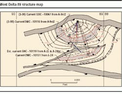
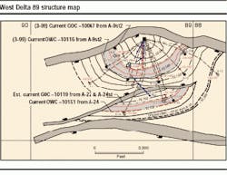
The West Delta 89 field is located in the Gulf of Mexico 200 miles southeast of New Orleans in 210 ft water depth. The field was discovered in 1988 and resulted in the setting of a 28-slot, eight-pile platform. Twenty-four wells were drilled prior to production startup in March 1991. Agip Petroleum assumed operatorship in December 1991. There are 18 producing wells, two water source wells, and four water injectors.
Re-entry of the existing wells at West Delta 89 provided two viable approaches. The first option required milling a window (or cutting a section) in the production casing, sidetracking with high buildup rates, and drilling the horizontal laterals without running casing through the upper formations.
The second option was to cut and pull the production casing to enable drilling a larger hole and reduce the buildup rates, case off the upper formations and the gas cap, then drill the laterals.
Operational concerns regarding the successful operation of the casing milling option and subsequent drilling operations included:
- Drill string performance due to high torque and drag
- Ability to rotate steerable motors through large doglegs
- Compromised hydraulics due to pump limitations
- Dependability of small diameter measurement-while-drilling (MWD)/logging-while drilling tools (LWD)
- Placement of sidetrack cement plugs in a slimhole
- Drilling the horizontal lateral with a solids laden drill-in fluid
- Higher mud weights (due to the build section being exposed)
- Isolation of the shallower formations from the oil column
- Compromised gravel-packing operations with small tubulars.
Ultimately, the second option (cut and pull casing versus mill a window or section) was utilized for designing both wells, although the estimated cost for the cut and pull operation was 18% higher than the casing milling operation.
Well A-9
Operations began on the A-9 well on January 31, 1999, to recover the slot, drill an expendable pilot hole, plugback and sidetrack, drill a horizontal lateral, and complete the well. The drilling rig was released from the well on April 5, 1999. The well was completed 12.4% under budgeted appropriations for expenditure.
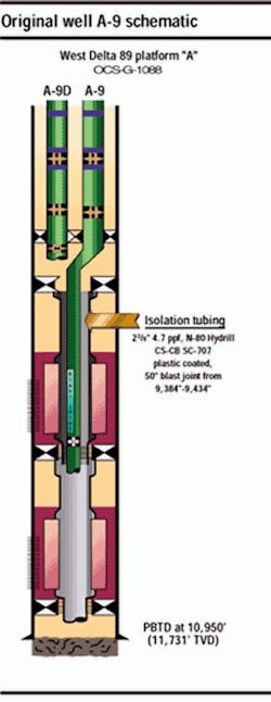
Well A-9 was originally a dual completion in shallower sands. The short string was on production but was a marginal producer. The long string had been off production since 1994.
The A-9 slot recovery operations consisted of abandoning and isolating the two producing zones, then retrieving the upper portion of the 7-in. production casing to drill a 9 7/8 in. hole below the 10 3/4 in. surface casing. The abandonment operations and initial casing retrieval work was performed rigless with the platform crane, slickline unit, cementing skid, and casing jacks. A jackup drilling rig was utilized to recover the remaining casing, due to better operating efficiency.
On the A-9 pilot hole, a slick BHA was utilized to dress the kick-off plug that was set above the 7-in. casing stub. A steerable motor with a 9 7/8 in. mill tooth bit was used to sidetrack the hole. A gyro was initially used during the kick-off, due to the proximity of the A-9 well to two others. Surveys for the remainder of the hole were obtained from a directional MWD tool.
An expendable pilot hole, the A-9 (ST No. 2) was drilled to determine the top and the base of the target sand and the gas/oil and oil/water contacts. Directional drilling operations were conducted on the 9 7/8 in. wellbore without major incidents.
The A-9 pilot hole was nudged towards the southwest (235 degrees azimuth), and then the inclination angle was built from 0 degrees to 30 degrees, while turning the azimuth to 180 degrees. After drilling several hundred feet with a constant angle and direction, the hole was turned back to azimuth of 240 degrees, so that the pilot hole would be correctly oriented to encounter the gas/oil and oil/water contacts.
After finishing the azimuth turn, a trip was made for a four bladed polychrystalline diamond compact bit and to place a resistivity/gamma ray LWD tool in the bottomhole assembly. Prior to penetrating the lower "P" sand, the inclination angle was dropped to approximately 14 degrees, while maintaining the hole azimuth of 240 degrees. The hole was drilled to a total measured depth of 10,832 ft through the lower "P" sand.
After logging the pilot with pipe conveyed logging tools, the preliminary plan of the horizontal wellbore remained virtually unchanged. The pilot hole was then abandoned with a cement plug set across the lower 'P' sand.
Build to horizontal
In building the A-9 well to horizontal, the sidetrack plug was dressed with a slick bottomhole assembly (BHA), then a steerable motor and a directional MWD tool were utilized to kick-off the A-9 (ST No. 3) with a four-bladed PDC bit. A trip was made to pick up a mill tooth bit, re-configure the steerable motor, and pick up a triple combo LWD tool.
The inclination angle was built to 90 degrees, along an azimuth of 300 degrees with an average buildup rate of 5 1/2 degrees per 100 ft. The hole was successfully landed within the 6-ft target on the first attempt. While drilling the final build curve, 47% of the drilling time was spent sliding the motor.
A hole opener trip was made, then the wellbore was cased off and cemented with 7 5/8 in. production casing. Prior to drilling the lateral section, several calculations were performed to ensure that the lateral would remain within the sand body, regardless of any variations of the formation dip angle or the direction of the strike. No further adjustments were made.
In the A-9 horizontal drilling, a non-damaging drill-in fluid was displaced into the well utilizing an indirect displacement method. After displacing the hole to a drill-in fluid, a 500-ft lateral was drilled with a 6 3/4 in. mill tooth bit using a steerable motor and resistivity/gamma ray tool.
The vertical window for the lateral was 10 ft, due to its close proximity to the gas cap and water leg. The entire lateral was successfully maintained within this window with a minimal amount of directional work (6.5% of slide time).
The drill-in fluid was displaced to completion brine utilizing flow rates that achieved annular velocities of 300 ft/min in the open hole to remove the static filter cake from the sand face of the wellbore. The brine density was selected to maintain an overbalance condition greater than 350 psi, to keep the dynamic filter cake in place. A 4-in. prepacked screen was set in the open hole, and the horizontal lateral was gravel packed (water packed) without any problems.
After running the 2 7/8 in. production tubing, the well was put on production with a rate of 1,300 b/d, which was determined optimum to delay water coning.
Well A-21
Operations began on the A-21 well on April 5, 1999, to reclaim the slot, drill an expendable pilot hole, plugback and sidetrack the hole, drill a horizontal lateral, then complete the well. The well was completed without major incidents at 25.2% under budgeted AFE benefiting in part from the "learning curve" estabilish from the A-9 operations. The drill rig was released on May 24, 1999.
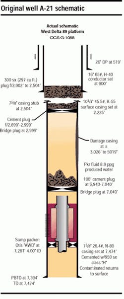
Well A-21 was originally completed as a water source well as part of the waterflood operations initiated to maintain reservoir pressures within the producing zone. During a routine workover in 1995, the production casing was damaged. The lower portion of the well was abandoned with retainers and cement after which a dry hole tree was installed.
Slot recovery
A-21 well slot recovery operations consisted of retrieving the upper portion of the 7 5/8 in. prod-uction casing with the drilling rig to enable drilling a 9 7/8 in. hole below the 10 3/4 in. surface casing. The kick off plug set above the 7 5/8 in. casing stub was dressed with a slick BHA, then a steerable motor with a 9 7/8 in. mill tooth bit was used to sidetrack the hole. A directional MWD tool was positioned in the BHA for taking directional surveys.
An expendable pilot hole was drilled to determine the gas/oil contact in the reservoir (the oil/ water contact had been periodically monitored with pulse neutron logs). Directional operations for the pilot hole were conducted in a 9 7/8 in. hole without problems, using a steerable motor in the upper hole, and the AutoTrak rotary closed loop-drilling system in the lower part of the hole.
The A-21 (ST No. 1) pilot was nudged toward the southwest (203 degrees azimuth) to avoid an adjacent well, then the inclination angle was built from 12 degrees to 34 degrees. The inclination angle and azimuth were kept constant over the remainder of the bit run. The penetration rate with the mill tooth bit was 80% faster on the A-21 well, compared to A-9.
The AutoTrak rotary steerable drilling system (with a resistivity/gamma ray module) was run with a four-bladed PDC bit. The hole was turned to an azimuth of 130 degrees, then the inclination angle and the azimuth were held constant to a measured depth of 11,945 ft. After drilling through the lower "P" sand, additional footage was drilled to provide a rathole for logging.
A triple combo log was run on drill pipe and confirmed the location of the gas/oil contact. The vertical positioning of the horizontal lateral was selected and the orientation to the lateral adjusted slightly.
A-21 build
The preliminary directional plan for drilling the A-21 (ST No. 2) horizontal sidetrack hole was adjusted by positioning the landing depth of the lateral 27 ft higher than originally planned, based on the information from the logging run. The remaining directional work to turn the hole, while building the inclination angle to 90 degrees in a 3D plane, was unchanged. Vertical tolerance in the horizontal lateral was increased from 20 ft to 22 ft.
The pilot hole was abandoned with a cement plug set across the lower "P" sand. After dressing the plug with a slick BHA, the AutoTrak drilling system with a four-bladed PDC bit was run in the hole. The inclination angle was initially maintained at 30 degrees while the azimuth was turned 75 degrees (to a 131 degree azimuth) utilizing an average buildup rate of 3.6 degrees per 100 ft. An industry milestone was reached by using the AutoTrak rotary closed loop steerable system for the first time to kick off a directional hole in a soft, unconsolidated formation.
Once a tangent section was drilled, the inclination angle was built from 30 degrees to 90 degrees, while turning the azimuth 30 degrees (to an azimuth of 101 degrees) using a build-up rate of 4.4 degrees per 100 ft. In the midst of the final approach, it was determined that the heel was not properly positioned for the landing.
Several calculations were performed, which suggested an additional 10 degrees of turn was necessary (to an azimuth of 91 degrees) to ensure that the horizontal lateral would remain within the sand body, regardless of any minor variation of the formation dip. The hole was landed in the oil column on the first attempt with the AutoTrak system, within a vertical tolerance of 5 ft. A string of 7 5/8 in. production casing was set and cemented to protect the build curve and to isolate the gas cap.
In horizontally drilling the A-21 well, a non-damaging, drill-in fluid was displaced into the well using an indirect displacement method. The entire lateral was successfully maintained within a vertical window of 22 ft.
The heel of the lateral was positioned near the top of the target with the toe located near the bottom of the target. The horizontal lateral was drilled with an average drop rate of 3/4 degree per 100 ft, while rotating the steerable motor the entire time (0% slide time). Location of the toe was 12 ft deeper than the heel.
After drilling operations were completed, the drill-in fluid was displaced to completion brine utilizing flow rates that achieved an annular velocity of 300 ft per minunte in the open hole to remove the static filter cake from the sand face. The brine density was selected to maintain an over-balance condition greater than 350 psi to keep the dynamic filter cake in place.
A 4-in. pre-packed screen was set in the open hole, and the horizontal lateral was gravel packed (water packed) without any problems. After running the 2 7/8 in. production tubing, the well was put on production with a rate of 1,300 b/d.
The offset wells were drilled with mud weights between 9.8 ppg to 10.5 ppg. Pore pressure plots that were generated from several offset logs confirmed that the majority of the hole would be in the normally pressured regime. One concern raised during the planning stages was whether lost circulation would occur in any of the partially depleted areas. Five sands are in the producing horizons in the field, and measured bottom hole pressure data showed a slight decline in the reservoir pressures due to production.
A water based drilling mud was utilized to drill the 9 7/8 in. hole section (pilot and horizontal sidetrack) in the A-9 and A-21 wells. Adequate performance of this fluid was obtained with the chemical additives ensuring that the complex directional profiles could be drilled with minimal hole problems. An inhibitive water-based drill-in fluid, KCL base fluid with biopolymer and starch, was utilized to drill the 6 3/4 in. horizontal lateral.
Completions
The horizontal laterals in both A-9 and A-21 wells were completed with an open hole horizontal gravel pack. Based on the production rates and reservoir pressure measurements, the goal of obtaining a low skin, high efficiency completion was achieved. These two OHGPs were the first such completions worldwide for ENI/Agip.
After drilling the lateral section with the inhibited water based drill-in fluid system, this fluid was displaced to KCL completion brine utilizing a pump rate of 10 bpm. This rate enabled a velocity of 300 ft. per minunte to be attained in the open hole and provided adequate energy for displacing the open hole and removing the static filter cake from the sand face of the wellbore.
The 8.7 ppg brine density maintained an overbalanced condition exceeding 350 psi to enable the dynamic filter cake to be held in position during the well displacement.
A 4-in. pre-packed screen was set in the entire open hole and extended approximately 30 ft into the 7 5/8 in. production casing. Once the screen was landed and packer set, gravel-packing operations began. Initial circulating rates between 1/2 bpm to 5 bpm were taken with virtually full returns; thus the job design was limited to a maximum pumping rate of 5 bpm (circulating rates greater than 5 pbm resulted in partial returns). The gravel pack was pumped with 1 ppg sand concentration on both wells, and sand out was achieved as planned on each job. A flapper valve was installed above the prepacked screen to eliminate excess brine losses into the formation after concluding gravel packing operations.
A string of 2 7/8 in. 6.5 ppf L-80 BTS-8 prod-uction tubing with gas lift mandrels was run in the well, and a 2 1/2 in. single christmas tree was installed. Several of the dummy valves in the mandrels were replaced with live valves, and both wells were put on production with minimal drawdown pressures.
Conclusions
The work described demonstrates that with open communication in the planning and execution phases, advanced drilling and completion technology can be applied successfully on the first attempt. The results of this field redevelopment have shown that:
- Re-entry horizontal wells can be drilled and completed successfully with challenging, complex directional profiles in relatively slim holes.
- Open hole gravel pack is a viable alternative to cased, cemented, and perforated gravel packing operations in unconsolidated formations.
- Re-entry drilling and OHGP technology have viability in redevelopment projects were perceived, marginal economics exist.
- Steerable rotary assemblies can be used successfully to kick off wells in soft, unconsolidated formations.
- Water-based drill-in fluids are viable for use in horizontal laterals where depleted zones may exist.
- Displacement to the completion brine utilizing high annular velocities (300 ft/per min-ute) are paramount in providing adequate energy for displacing the hole and removing static filter cake from the sand face.
- Hydrostatic pressure must be kept on the hole while displacing the drill-in fluid to completion brine, deploying the gravel pack assembly and during gravel placement to ensure that the static filter cake is maintained on the borehole wall and fluid loss is kept to a minimum.
Acknowledgement
Agip Petroleum and Baker Oil Tools agreed to publish this paper. Gildo Possamai, Agip Petroleum's Well Operations Manager, provided direction and coordination for this project. Personnel from Agip Petroleum, F. J. Brown and Associates, Inc., Baker Oil Tools, Baker Hughes Inteq, Hughes Christensen, Baker Atlas, and Noble Drilling helped make this redevelopment a success.


