Horizontal casings/liners can be cemented with success equal to that of vertical ones
S. A. McPherson
BJ Services Co. Ltd
Cementing horizontal wellbore casings and liners with success equal to that experienced in installated vertical prod-ucts has been achieved in North Sea wells. Cementing practices and proce-dures have been developed on a number of BP Amoco Wytch Farm wells.
Since BP Amoco's extended reach drilling work started at Wytch Farm in 1993, the firm has continually increased the boundaries of horizontal drilling, most recently completing well number 1M-18-SP (SPE 62893). The longest well drilled from M-Site was 1M-16-SP. An outline of the wellbore follows:
- Vertical pre-set 26 in. conductor at 25 meters
- 18-5/8 in. casing set at 260 meters within the Top Chalk
- 13-3/8 in. casing set within the Oxford Clay at 1,009 meters measured depth and 764 meters vertical depth
- 9-5/8 in. casing being set in the Top Sherwood reservoir at 7,451 meters measured depth and 1,590 meters vertical depth
- 8-1/2 in. section to a total depth of 11,278 meters, making this the world's longest horizontal section to date
- 7 in. liner set at vertical depth of 1,610 meters and a total depth of 10,210 meters.
Four wells in excess of 9,000 meters measured depth were drilled and cemented.
Spacers and pre-flushes
It is accepted throughout the industry that increased displacement and circulation rates offer direct improvements in mud removal, allowing better bonding to pipe and formation and improved zonal isolation. All the liner cement jobs in the Wytch Farm development have used large volumes of spacers and pre-flushes.
At the start of the extended reach drilling work, liner wellbores were prepared for cementing. A base oil pre-flush followed by a weighted water based spacer, at about halfway between the mud and cement densities, was used.
This system had repeatedly provided the cement slurry with a substantial base for good bonding to the pipe and formation. As indicated by the cement bond logs run on wells M08 and M10, no remedial work has ever been required. At this time, the average displacement rate for liner jobs was in the region of 6-8 bpm.
During planning for well M11 (the first well with a liner set at +10,000 meters measured depth), it was noted that the displacement rate would have to be reduced to approximately 4 bpm to ensure the fracture pressure of the formation was not exceeded during cementing.
Slurry design
The extended reach work has all been done at vertical depths of less than 1,800 meters and a reservoir temperature of 150-165
Although land based, this area does not have a ready supply of fresh water. The 16-ppg slurry density ensures the generation of a sheath of cement with competent compressive strength development to properly support the casing.
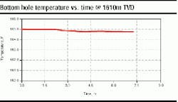
In order for the laboratory testing to closely simulate circulation along the extended horizontal section, the API temperature tables detailed in Spec. 10a are only used to determine the bottomhole static temperature (BHST). The calculation of the bottomhole circulating temperature is based on the assumption that at some horizontal distance from a vertical wellbore, cold fluids pumped from surface will have been exposed to the well temperature for sufficient time to warm up to BHST conditions.
As a result of this, it is assumed all fluids will reach the bottomhole static temperature by the time they are displaced to the total measured depth of the well. To simulate this, all laboratory work is carried out at ambient (surface conditions) and bottomhole static temperatures. This assumption has been verified using a computer based well temperature simulator.
Inherent with the extended length of both 9 5/8-in. casing strings and the liners, is the requirement for extended slurry-thickening times to compensate for the large displacement volumes. In addition, real well situations can be different from the simulated ones and a long thickening time allows the displacement rate to be reduced, if required, during the job.
Slurry thickening
Building in safety margins to slurry thickening times allows the cementer and rig site personnel to deviate from the simulated program, if well conditions dictate. This flexibility can be used, for example, to heal a fracture created during cementing in a previously unseen weak spot, by reducing pump rate, and therefore ECD (equivalent circulating density).
On average, liner slurry designs have a thickening time of 10 hours, with the cement job taking in the region of 5-7 hours. The cement slurry used on the liner for well 1M-16-SPz had a thickening time of 15 hours, with the job taking 8 1/2 hours to complete.
Cement slurries with long thickening times, tested at BHST inherently take a long time to set when in the annulus. This has an effect on more than just the drill-out time of the shoe or when the liner lap can be pressure tested. Having the slurry in a liquid state for extended periods downhole can lead to increased free water generation and solids segregation.
Free water generation by cement slurries in horizontal sections can be more detrimental to the overall annular isolation than the same percentage loss from slurries in vertical wells. In vertical wells, any free water released by the cement will migrate to the top of the cement column, resulting in the potential formation of fluid channels and poor wellbore isolation.
Unless the free water generation is very high, this effect does not greatly influence vertical work. In horizontal wells, the top of the cement column runs the full length of the wellbore and any free water generated will result in poor bonding and possible communication along the high side of the wellbore.
Loss of mix water
Loss of mix water from the slurry, during displacement, will reduce the slurry's thickening time and increase its viscosity. As the slurry loses water, it will lay down a filter cake against the permeable formation wall. Uncontrolled, this will change the flow regime of the slurry from the calculated one to some unpredictable alternative and may result in excessive ECD being experienced during displacement.
The filter cake will continue to grow over the whole length of the permeable zone, and in extreme cases may result in a total blockage of the annulus, preventing further displacement. To reduce the amount of fluid lost from the slurry to the permeable reservoir section, liner slurries
must have an API fluid loss of less than 80 mls in 30 minutes, tested with a differential pressure of 1,000 psi and at bottomhole static temperature. This level of fluid loss from the slurry generates a thin sacrificial filter cake, which prevents further loss of fluid from the slurry during displacement. The field is oil producing and does not have a requirement for gas migration control within cement slurries.
API rheology measurements are taken using a standard Fann 35 rheometer, at ambient and bottomhole static temperatures. These readings are used to determine a number of characteristics about the fluid. Its ease of mixing at the cement unit is of paramount importance as stoppages during mixing and pumping will interrupt the planned flow regimes of fluids already in the pipe and annulus.
The fluid model that best represents the slurry can also be calculated and used to predict, among other things, expected pressures during the job and hole cleaning abilities. This information can then be used to determine optimum pump rates and spacer designs. For speed, the figures can be incorporated into a computer-based job simulation program, which generates information on more than just the critical factors stated above.
Wellbore considerations
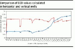
The ECD values seen while cementing horizontal wells vary greatly from those experienced with vertical wells. The graph compares these values calculated during the displacement of a horizontal well (demarked by squares) with those for a vertical well of the same length (demarked by triangles) using the same fluids and displacement rates. As can be seen the vertical well exhibits lower ECD's for the majority of the job but these rise by the end of the displacement to almost 0.7 ppg higher than those seen in the horizontal well. This is due to the hydrostatic weight of the fluids having greater influence in the vertical instance.
However, in a horizontal well, the weight of the fluids in the liner or casing, are spread along the length of the hole. Centralizers applied using spacing that will support the casing off the bottom of the hole would have to be increased in number to support the extra weight of the cement in the casing.
Regardless of well geometry, a minimum API stand-off of 67% is recommended to obtain a sound cement job. This amount of clearance from the wellbore allows sufficient access around the casing for good mud removal and correct cement placement. When cementing liners, many operators and service companies recommend a higher stand-off of 80% to ensure high quality cement job.
As the deviation angle increases, the number of centralizers required to achieve these stand-off figures also increases. In addition, compressible (bow type) centralizers have to overcome the weight of the pipe as it lies along the low side of the well. This extra strain on the restoring force results in each centralizer contributing less to the "lift" of the casing or liner from the low side of the wellbore. In extreme cases, the standoff achieved will be lower than the minimum API recommendation, perhaps only 60%. In response to the solid centralizers that are not limited by restoring forces are used in highly deviated and horizontal wellbores.
Liner jobs for the project have used solid centralizers from the outset of the extended reach program. They were applied at 2 per joint over the whole length of the liner and generated up to 90% stand-off. As the horizontal sections extended the forces required to run all these centralizers became too great. Latterly, they were only used over intervals, which required a particularly high degree of zonal isolation.
Movement of the pipe, during pre-job circulation and cementing, either by reciprocation or rotation has long been accepted by the industry as beneficial to primary cementing operations. Moving the pipe has been shown to improve cuttings and filter cake removal, and help break down mud gel.
These advantages continue to hold true when considering horizontal or highly deviated wells. However, due to the nature of the wellbore, pipe tends to lie along the bottom introducing additional torque and drag forces, which must be overcome.
For these reasons most liners are now set and released before pumping cement, and whenever possible, rotated. In addition, when the casing/borehole relationship is severely eccentric, rotation appears to be more beneficial than reciprocation. Rotation of the pipe requires sufficient torque to overcome the downhole forces. These include:
- Weight of the pipe (which is lying on the low side of the open hole with little or no buoyancy)
- Weight of the cement slurry before it leaves the pipe
- The inherent restrictions associated with any centralizers.
Computer simulations
Excellent wellbore isolation has primarily been successful through the application of good cementing practices. Due to the limitations on reciprocation of the pipe and the low fracture gradient of the formation, annular cleaning has been achieved by other techniques. Implementation of the multiple spacers, each with a different flow regime, has allowed improved hole cleaning, while reducing the placement ECD. The thin low fluid loss slurry is easy to mix and pump, yet provides excellent zonal isolation and pipe support.
The ability to simulate the job on computer ensured that the fluid's rheology and density are beneficial to the job objectives and the effects of any changes are accounted for. In addition, the novel use of centralizers with rollers during well 1M-16-SPz allowed this long section of pipe to be rotated for the majority of the cement placement process.
Acknowledgement
BJ Services Co. Ltd. and BP Amoco and partners in the Wytch Farm oilfield granted permission to publish this work. Thanks also to Steve Gill, Dan Daulton, and Graham Want (Sr. Service Supervisor) of BJ Services Co. Ltd.
Author's Note: In the text, reference is made to API Spec 10a dated 1991. Please note that this was the most recent issue of the specification at the start of the project and that test procedures have been continually compared against more recent issues, as they have become available.


