Deepwater drilling analysis tool addresses wellhead/conductor strains
GoM experience underlines need for more detailed evaluations
Michael Lane
Wood Group Kenny
Ultra-deepwater capacity semisubmersibles and drillships can operate in water depths of up to 12,000 ft (3,658 m). At these depths, more complex and heavier BOP stacks are required. The wellhead and conductor system is the key load-bearing structure that supports the BOP and the various casings that collectively link the hydrocarbon reserve to the drilling rig or vessel. It must ensure stability and structural integrity of the well for the duration of drilling operations in order to avoid critical failures.
Many modern ultra-deepwater rigs are equipped to accommodate 20,000-psi (1,379-bar) capacity BOPs with up to seven shear/seal rams, typically 45-55 ft (13.7-16.7 m) tall and weighing up to 800 kips. A larger BOP means more bending on the wellhead due to the higher elevation of its top section, and increased P-d effect as the heavy weight is shifted off-center.
This combination can also shift the natural period of the BOP/wellhead/conductor assembly into the range of typical wave periods, leading to increased dynamic effects from wave frequency loads.
Fatigue caused by the transmission of cyclic loading (bending and tensile) from the vessel and riser system into the wellhead or conductor is a major concern, which needs to be addressed through accurate estimation of the potential impact in the design of these components.
Intuitive interface
Wood Group Kenny has updated its DeepRiser software to provide enhanced capabilities in wellhead and casing modeling. The software is a Windows-based tool developed specifically for the analysis and design of drilling risers. It combines an intuitive user interface that simplifies building the riser model with a comprehensive finite element structural analysis methodology.
Traditionally drilling riser analysis models did not include wellhead and casing at all, or modeled them as single-bore tubulars. But the loading transmitted to these components in deepwater and ultra-deepwater systems necessitates a new approach.
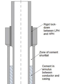
To accurately simulate the behavior of the wellhead, it is modeled as two sections: the high-pressure wellhead (HPWH) and low-pressure wellhead housing (LPWHH). The user inputs properties for the HPWH section, which runs the full length of the wellhead, and for the LPWHH section, which covers the HPWH from the bottom of the wellhead to a specified elevation. The overlap region is then modeled using a composite section approach.
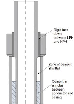
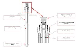
A single line of finite elements runs from the bottom of the wellhead to the top of the LPWHH region. This set of elements is assigned equivalent properties, calculated automatically and without user intervention from the user inputs. This composite model approach is acceptable because the wellhead is being analyzed in “rigid lockdown” mode, whereby the HPWH is landed and locked onto the top of the LPWHH with no relative motion between them.
A similar composite approach can be employed for modeling casing, in which separate properties input by the user for the various casings and cement are automatically combined to define properties for an equivalent single tubular. Given the potential multiplicity of layers, these calculations must be performed carefully to deliver a realistic model. Having the calculations done internally by the software minimizes the potential for user error.
A second, more complex casing modeling option involves a pipe-in-pipe approach. In this case separate lines of collinear elements are applied to model the individual casing layers. The properties of each set of elements correspond to the user-specified properties for that layer.
The additional mass per unit length of the cement and the contribution of the cement to bending stiffness is automatically added in. Interaction between layers is controlled by the specification of pipe-in-pipe connections, basically non-linear springs.
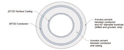
The composite and pipe-in-pipe models show close agreement for the majority of cases. However, in certain instances the pipe-in-pipe model offers a distinct advantage. One is a cement shortfall which occurs when cement in the annulus between the outer conductor and inner casing does not extend to the full height of the area of overlap between them. When that happens, there is no load share between conductor and casing in the shortfall section. The pipe-in-pipe model can be used to accurately model this scenario.
GoM experience
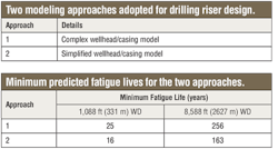
Recent drilling riser design experience of Wood Group Kenny engineers in Gulf of Mexico locations in both shallow water (1,088 ft/331 m) and deepwater (8,588 ft/2,617 m) allowed a comparison of the varying levels of complexity provided by DeepRiser. The key parameter examined was the minimum fatigue life along the casing and wellhead. Two modeling approaches were adopted:
In Approach 2, the casing model was one where only the conductor casing was accounted for. For the complex wellhead/casing model in Approach 1, the casing was assumed to be cemented back to the seafloor, so the composite casing model was employed everywhere: no pipe-in-pipe modeling was used.
When the outer conductor casing layer alone was included in the model, the estimated fatigue life was roughly 50% less than when both the conductor and surface casing layers were included. This finding underlines the importance of detailed modeling in modern drilling riser analysis. •