Cuttings transport model shown to decrease certain drilling risks
Eric Cayeux
International Research Institute of Stavanger
Amare Leulseged
International Research Institute of Stavanger
Roald Kluge
Statoil
Jarle Haga
Repsol
Transient cuttings transport models (TCTM) can be used to assist the planning and the execution of drilling operations, especially for long and complex wells. Drilling problems such as pack-offs, excessive torques, overpulls, or setdown-weights can result from poor hole cleaning.
The movements of cutting particles along the annulus depends on several factors such as the wellbore trajectory, the borehole and drillstem diameters, the drilling fluid properties, and drilling parameters such as the flow rate, drillstring rotational speed, and the rate of penetration. Thus, modeling the precise movements of the cutting particles considering the above constraints can help minimizing immediate and delayed drilling operations problems.
After reviewing important features necessary for a transient cuttings transport modeling, this article will present two example cases of the use of such a model.
Cuttings transport model
To circulate cuttings particles out of the well, a force should be applied to overcome the effect of gravitation that pulls the solid particles to the low-side of the borehole. This force is induced by the viscous friction generated by the relative movement of the drilling fluid compared to the surface of the particles. This force can be decomposed into a drag and a lift component, which depends on the local fluid velocity field (including whether the flow is laminar, transitional, or turbulent), the fluid effective viscosity, the drillstring eccentricity, and its rotational speed. The resulting movement of individual cuttings particles along a length of borehole is complex. However, there is a minimum bulk fluid velocity, called critical transport fluid velocity (CTFV), for which each cuttings particle is directly transported by the flow. In addition to the aforementioned factors, the CTFV depends on the particle dimensions and density, and the wellbore inclination. With fluid velocity below the CTFV and with inclination higher that 35°, cuttings may start to settle on the low-side and accumulate in a cuttings bed. This reduces the available passage for the fluid. Thus, the fluid velocity increases while the sedimentation of cuttings particles reduces.
Drilling fluids are viscoelastic, behaving like a viscous fluid during circulation and like an elastic solid when at rest. This property is crucial for keeping cuttings particles in suspension when the circulation stops. However, because of momentum and fluid compressibility, the fluid velocity decreases relatively slowly when the mud pumps are stopped. As a consequence, cuttings particle that were directly transported prior to the change of flow-rate, may reach the low-side of the borehole, in highly inclined sections of a well, before the drilling fluid gelation has had a chance to stop the particle movement.
Based on those principles, and together with a transient hydraulic model, drillstring mechanical model, and heat transfer model, it is possible to estimate how cuttings particles are transported into a borehole as a function of the applied drilling parameters.
Such a model has been used in two different contexts. In one case, it was used to compare the potential performances of different drilling fluids prior to the drilling of an 8½-in. section of an extended-reach drilling (ERD) well. It led to the choice of a drilling fluid system for the coming drilling operation. In the other instance, the model was used to post-analyze a difficult drilling operation performed in a tapered wellbore architecture, showing that there were natural causes to the problems that had been encountered during drilling and running in hole with a liner.
This methodology has also been used to assist in decision-making while drilling, but that will not be covered in this article.
Fluids evaluation study
An ERD well was being drilled from a fixed platform with an integrated drilling facility package which was about 25 years old. All the conductors ran directly from the platform’s wellhead deck, surmounted by a high-pressure riser, a BOP stack, and a low-pressure riser. The top-drive could deliver at most 60 kN.m at high rotational speed, but higher torque values could only be obtained below 120 rpm.
During the drilling of the 12¼-in. section, torque limitations required the top-drive speed to be reduced to 120 rpm. These limitations also caused severe cuttings transport problems, noticeable through continuous pack-off tendencies. Furthermore, it was not possible to rotate the top-drive at a high speed while cleaning the hole just before pulling out of hole and several overpulls were observed indicating that cuttings beds had been left in the borehole.
As the 8½-in. section was 1,750 m (5,741 ft) long, there was a concern that similar problems could be encountered, with the potential risk of losing the section. It was therefore decided to evaluate which of two mud systems would provide the least risk levels for hole cleaning. The originally planned mud was standard synthetic base mud (SBM) that will be referred to as SBm1. The second alternative was based on micron-size barite particles and will be denoted as SBm2.
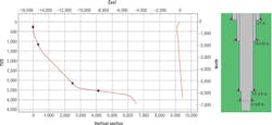
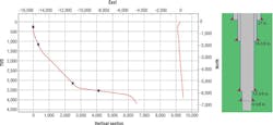
The well was a side track of an existing well with a 13⅜-in. casing installed at 4,277 m (14,032 ft) measured depth (MD) (3,207 m total vertical depth, TVD) at an inclination of 51°. The 12¼-in. section was drilled slant to 6,500 m MD (21,325 ft or 3,571 m TVD) after increasing the inclination to 84° utilizing a dogleg severity (DLS) of 2.5°/30 m (98 ft). A 9⅝-in. casing was ran and cemented to the end of the section. The plan was to drill the 8½-in. section starting at the same inclination for 1,125 m (3,691 ft), and then drop to 40° using a curvature of 2.2°/30 m to the section target depth at 8,250 m MD (27,067 ft MD or 4,000 m TVD).
The downhole pressure and temperature conditions at target depth were expected to be up to 700 bar (10,153 psi) and around 150°C (302°F), therefore indicating conditions that are very close to high-pressure/high-temperature.
To determine the risk levels for each mud systems, the first step was to determine the maximum flow rate that would be possible to use without exceeding the certification limit of the pumping system. After application of a safety margin, the calculations showed that toward the end of the section, the flow rate would be limited to 1,800 l/min for SBm1 and 2,100 l/min for SBm2 in order to avoid exceeding 300 bar (4,351 psi) at the mud pumps.
Note that the two fluids had equal mud density of 1.68 sg at atmospheric pressure and 60°C (140°F) and similar pressure volume temperature behavior. However, they had dissimilar rheological properties. SBm2 was much less viscous than SBm1, but also its effective viscosity did not depend as much on pressure than the standard SBM, even though both fluids rheological properties depended greatly on temperature. As could be expected, the simulations also showed that the downhole pressure variation as a function of flow rate would be more limited for SBm2 than for SBm1.
Assuming a minimum fracturing pressure gradient of 2.02 sg for the open hole section, it would have been very easy to fracture the well with SBm1 with even as low a flow rate as 1,600 l/min.
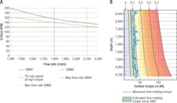
Torque and drag calculations for the 8½-in. section showed that the free rotating torque would be between 50 and 75 kNm when using SBm1, while it would be significantly lower when using SBm2 (from 40 to 50 kNm as a function of the bit depth). This means that using SBm2 could allow to maximum rotational speed all the way down to the section target depth while SBm1 would probably require to reduce the top-drive speed toward the end of the section.
Based on the model, a critical top-drive rotation speed required to transport cuttings has been calculated. For SBm1, the maximum flow rate would be limited to 1,800 l/min because of the pump pressure, and it would be necessary to rotate the drillstring above 160 rpm in order to transport the cuttings in the near horizontal parts of the well, which is obviously incompatible with the torque limit that was discussed just above. On the other hand, the maximum allowable flow rate with the SBm2 would be around 2,100 l/min and the corresponding critical drillstring rotation speed would slightly be above 120 rpm and therefore be compatible with more demanding torque conditions than anticipated.
Based on the findings of the study, the decision was made to use the SBm2 mud for the drilling of the 8½-in. section and the section was drilled without any problems. During the actual drilling process, the top-drive torque was reported to be below 50 kNm for the hole section, as predicted by the model.
However, the downhole ECD was observed to be higher than predicted by the model for the recommended flow rate of 2,000 l/min. Instead, 1,850 l/min was used, and the measured downhole ECD was within the range of 1,930 and 1,990 kg/cu m. The reason for the discrepancy was that the actual viscosity of the mud was larger than the one used during the study. Even though a lower flow rate was used, the fact that the drillstring could be rotated at high velocity allowed a proper transport of the cuttings.
North Sea case study
On a different fixed platform in the North Sea, the transient cutting transport model has been used to analyze the hole cleaning conditions of an 8½-in. drilling operation of a challenging well with a tapered casing architecture.
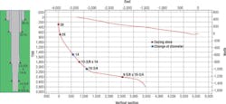
The tapered architecture was constituted of a 10¾ x 9-in. liner inside a 13⅜ x 14-in. casing. The objective of this large diameter borehole was to install an electrical submersible pump inside the 13⅜ x 14-in. casing at a maximum inclination of 40°.
This is part of the tail production of this mature field, where a forced depressurization of the reservoir is performed to increase the production of the remaining gas. The principle of this strategy was to decrease the reservoir pressure by pumping out water below the initial oil-water contact to release solution gas in residual and trapped oil that is uneconomic to produce or has been by-passed.
Description of well
For this particular well, the 13⅜ x 14-in. casing was set at 2,060 m MD (1,800 m TVD) with an inclination limited to 40°. This part of the well had a kick-off at 760 m MD (2,493 ft) that increased the inclination to 33° with a DLS of 2.7°/30 m. The angle was further increased to 40° over the last 330 m MD (1,082 ft) of the section with a DLS of 0.3°/30 m. With a target TVD at 2,800 m (9,186 ft), a second kick-off was necessary below the 13⅜ x 14-in. casing shoe in order to increase the inclination from 40° to 80° and a 10¾ x 9⅝-in. liner was set at 3,881 m MD (7,841 ft MD or 2,390 m TVD).
The 8½-in. section had a target depth of 5,000 m MD (16,404 ft). The section had a 560 m (1,837 ft) of tangent section at 80°, and then dropped to 40° over the remaining 440 m (1,443 ft) to reach the section target.
Analysis of operation
The operation started by drilling out the 9⅝-in. casing shoe and cement with 1,900 l/min flow rate and 60 rpm. The standpipe pressure started to fluctuate substantially by about 10 bars over a longer period of time and had pressure bursts of up to 20 bars (290 psi) over a few minutes. These over-pressures were accompanied by drops of free rotating weight by up to 15 tons. These are typical signs of bridging or pack-off situations. With the current drilling parameters, the TCTM estimated that two cuttings beds were forming, one inside the 9⅝-in. liner, and another one just above the 10¾-in. liner hanger. Measurements showed that there were very high levels of stick-slip and erratic downhole pressure, both facts were additional indications that a possible cuttings bed was forming inside the 9⅝-in. liner.
Before starting to drill the new formation, the well was circulated, and the downhole ECD dropped to values that were compatible with a cleaned hole.
When the drilling of the new formation started, the drillstring rotation and flow rate were increased first to 120 rpm and 2,100 l/min and then to 140 rpm and 2,200 l/min, respectively. With these drilling parameters, the TCTM showed that the cuttings bed inside the 9⅝-in. liner should no longer exist while the one just above the 10¾-in. liner hanger would continue to accumulate cuttings. After more than three hours of drilling into the new formation, the model showed that no cuttings had reached the surface.
This could be confirmed since the pit volume had not decreased even though 49 m (161 ft) of formation had been drilled since starting the section. If the cuttings would have been transported to the surface, they should have been separated by the shakers and since the bottomhole depth increased, it should have resulted in a pit volume decrease of 1.8 cu m. The model predicted that the first cuttings should have arrived on the shaker 16 hours after the drilling started, and that the amount of cuttings would be limited. Both the timing and quantity were confirmed by the pit volume decrease.
High stick-slips, in the range of 180 to 260 rpm, were observed during the drilling of the remaining section. However, the magnitude of the stick-slips decreased when the bottomhole assembly started to enter the dropping section (in the range of 20 to 90 rpm peak to peak while the top-drive speed was 160 rpm).
After reaching the target depth of the section, the well has been circulated clean and the downhole ECD decreased from 1.695 sg to 1.68 sg, which was still higher than the expected value of 1.64 sg. The transient cuttings transport model predicted that there should have been a 400 m (1,312 ft) long of cuttings bed inside the 10¾-in. liner section.
At the time of the drilling operation, the drilling crew thought that the well was clean and started to pull out of hole. Despite the fact that the model indicated that it was likely that a cuttings bed was left inside the 14-in. casing, the pull-out of the hole went smoothly, with a sliding friction starting at 0.2, decreasing to 0.15 over the first 300 m (984 ft), pulled, and stayed constant thereafter.
Even though the operation went without any problems, totally different observations were made while running the 7-in. liner. Past 1,500 m MD (4,921 ft), the apparent sliding friction increased to 0.3 and shortly after it continued to increase up to 0.4. As the liner passed the 10¾-in. cross-over at 2,500 m MD (8,202 ft), the apparent sliding friction continued to increase reaching values between 0.5 and 0.6, and then started to decrease slowly. When approaching the 9⅝-in. casing shoe, the sliding friction had decreased to 0.45.
A set-down weight was experienced at 4,350 m MD (14,271 ft) and it was not possible to pass that depth. As a result, back-reaming was initiated. While reaming up to the casing shoe large quantities of cuttings were transported to surface, which was visible by the decrease of the pit volume as cuttings got separated from the drilling fluid. When attempting to run in hole, the sliding friction had decreased to 0.2, and the liner could be landed and cemented without any problems.
The predictions made by the model that a large cuttings bed had been left during the hole cleaning operation at the end of the 8½-in. drilling operation was therefore indirectly confirmed by the problems encountered during the running in hole of 7-in. liner.
Conclusion
A first example has shown that a TCTM can be used to make important decisions in order to decrease the risk levels in complex drilling operations when the possible conditions are not very intuitive. A second example has shown that the transport of cuttings is a non-holonomic process and that it is important to track the whole history of the cuttings transport to evaluate the actual downhole conditions.
Acknowledgment
Based on paper SPE-178862-MS: “Use of a Transient Cuttings Transport Model in the Planning, Monitoring and Post Analysis of Complex Drilling Operations in the North Sea,” by Cayeux, E., Leulseged, A., Kluge, R., Haga, J. and presented at the SPE Drilling Conference in Fort Worth, Texas, USA, March 1-3, 2016.


